Description Resource Path Location Type make: *** No rule to make target 'main.o', needed by 'gpio_mio_interrupt.elf'. Stop. gpio_mio_interrupt C/C++ Problem
时间: 2023-09-07 14:15:43 浏览: 158
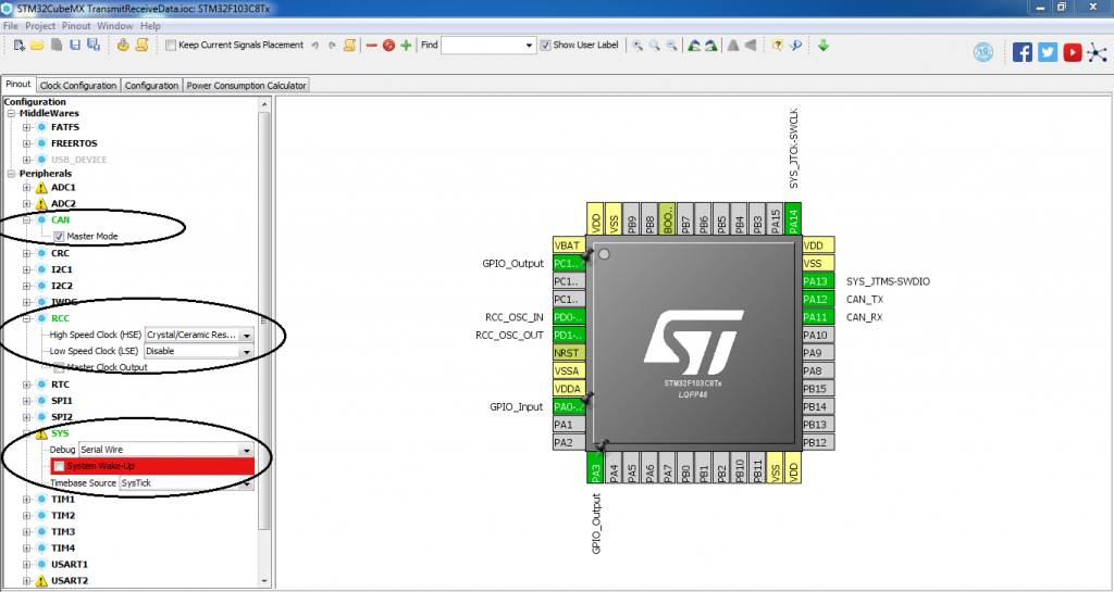
这个错误提示是在进行编译时出现的,它表明编译器找不到名为 "main.o" 的目标文件,因此无法生成名为 "gpio_mio_interrupt.elf" 的可执行文件。可能的原因是您没有正确地设置编译器选项或缺少了源文件。您需要检查编译器选项和源文件是否正确,并确保在编译之前已经生成了 "main.o" 目标文件。如果没有,请确保将 "main.c" 文件添加到项目中,并在编译器选项中正确指定源文件的位置。
阅读全文
相关推荐
大家在看
微软面试100题系列之高清完整版PDF文档[带目录+标签]by_July
本微软面试100题系列,共计11篇文章,300多道面试题,截取本blog索引性文章:程序员面试、算法研究、编程艺术、红黑树、数据挖掘5大系列集锦:http://blog.csdn.net/v_july_v/article/details/6543438,中的第一部分编辑而成,涵盖了数据结构、算法、海量数据处理等3大主题。
闲不多说,眼下九月正是校招,各种笔试,面试进行火热的时节,希望此份微软面试100题系列的PDF文档能给正在找工作的朋友助一臂之力!
如果读者发现了本系列任何一题的答案有问题,错误,bug,恳请随时不吝指正,你可以直接评论在原文之下,也可以通过私信联系我。
祝诸君均能找到令自己满意的offer或工作,谢谢。July、二零一二年九月二十日
HP 3PAR 存储配置手册(详细)
根据HP原厂工程师的指导,把每一步的详细配置过程按配置顺序都用QQ进行了截图,并在每张截图下面都有详细说明,没接触过3PAR的人用这个手册完全可以完成初始化的配置过程,包括加主机、加CPG、加VV、映射,另外还包括这个存储的一些特殊概念的描述。因为是一点点做出来的,而且很详细。
5G分组核心网专题.pptx
5G分组核心网专题
[C#]文件中转站程序及源码
在网上看到一款名为“DropPoint文件复制中转站”的工具,于是自己尝试仿写一下。并且添加一个移动文件的功能。
用来提高复制粘贴文件效率的工具,它会给你一个临时中转悬浮框,只需要将一处或多处想要复制的文件拖拽到这个悬浮框,再一次性拖拽至目的地文件夹,就能高效完成复制粘贴及移动文件。
支持拖拽多个文件到悬浮框,并显示文件数量
将悬浮窗内的文件往目标文件夹拖拽即可实现复制,适用于整理文件
主要的功能实现:
1、实现文件拖拽功能,将文件或者文件夹拖拽到软件上
2、实现文件拖拽出来,将文件或目录拖拽到指定的位置
3、实现多文件添加,包含目录及文件
4、添加软件透明背景、软件置顶、文件计数
中国电力建设协会 调试工程师题库
中国电力建设协会 调试工程师题库,本题库为电网专业 调试总工程师考试题库。有志于考取调总的,本题库十分有用。
最新推荐
使用GPIO模拟实现IIC Slave的方法及source code_1.docx
使用GPIO模拟实现IIC Slave的方法及源代码详解 本文档主要介绍了使用GPIO模拟实现IIC Slave的方法,并提供了详细的源代码分析和解释。本文档将涵盖IIC Slave的设计思想、程序设计、寄存器配置、核心代码分析等多个...
FL7102_2Q0+PS8742B+PS176_V1.0.pdf
在当前的数字化时代,Type-C转HDMI扩展坞已经成为许多用户和专业人士不可或缺的设备,用于将Type-C设备连接到高清显示器或投影仪。这个解决方案主要依赖于三个关键芯片:FL7102 PD芯片,PS8742 HUB芯片以及PS176 ...
易语言例程:用易核心支持库打造功能丰富的IE浏览框
资源摘要信息:"易语言-易核心支持库实现功能完善的IE浏览框"
易语言是一种简单易学的编程语言,主要面向中文用户。它提供了大量的库和组件,使得开发者能够快速开发各种应用程序。在易语言中,通过调用易核心支持库,可以实现功能完善的IE浏览框。IE浏览框,顾名思义,就是能够在一个应用程序窗口内嵌入一个Internet Explorer浏览器控件,从而实现网页浏览的功能。
易核心支持库是易语言中的一个重要组件,它提供了对IE浏览器核心的调用接口,使得开发者能够在易语言环境下使用IE浏览器的功能。通过这种方式,开发者可以创建一个具有完整功能的IE浏览器实例,它不仅能够显示网页,还能够支持各种浏览器操作,如前进、后退、刷新、停止等,并且还能够响应各种事件,如页面加载完成、链接点击等。
在易语言中实现IE浏览框,通常需要以下几个步骤:
1. 引入易核心支持库:首先需要在易语言的开发环境中引入易核心支持库,这样才能在程序中使用库提供的功能。
2. 创建浏览器控件:使用易核心支持库提供的API,创建一个浏览器控件实例。在这个过程中,可以设置控件的初始大小、位置等属性。
3. 加载网页:将浏览器控件与一个网页地址关联起来,即可在控件中加载显示网页内容。
4. 控制浏览器行为:通过易核心支持库提供的接口,可以控制浏览器的行为,如前进、后退、刷新页面等。同时,也可以响应浏览器事件,实现自定义的交互逻辑。
5. 调试和优化:在开发完成后,需要对IE浏览框进行调试,确保其在不同的操作和网页内容下均能够正常工作。对于性能和兼容性的问题需要进行相应的优化处理。
易语言的易核心支持库使得在易语言环境下实现IE浏览框变得非常方便,它极大地降低了开发难度,并且提高了开发效率。由于易语言的易用性,即使是初学者也能够在短时间内学会如何创建和操作IE浏览框,实现网页浏览的功能。
需要注意的是,由于IE浏览器已经逐渐被微软边缘浏览器(Microsoft Edge)所替代,使用IE核心的技术未来可能面临兼容性和安全性的挑战。因此,在实际开发中,开发者应考虑到这一点,并根据需求选择合适的浏览器控件实现技术。
此外,易语言虽然简化了编程过程,但其在功能上可能不如主流的编程语言(如C++, Java等)强大,且社区和技术支持相比其他语言可能较为有限,这些都是在选择易语言作为开发工具时需要考虑的因素。
文件名列表中的“IE类”可能是指包含实现IE浏览框功能的类库或者示例代码。在易语言中,类库是一组封装好的代码模块,其中包含了各种功能的实现。通过在易语言项目中引用这些类库,开发者可以简化开发过程,快速实现特定功能。而示例代码则为开发者提供了具体的实现参考,帮助理解和学习如何使用易核心支持库来创建IE浏览框。
管理建模和仿真的文件
管理Boualem Benatallah引用此版本:布阿利姆·贝纳塔拉。管理建模和仿真。约瑟夫-傅立叶大学-格勒诺布尔第一大学,1996年。法语。NNT:电话:00345357HAL ID:电话:00345357https://theses.hal.science/tel-003453572008年12月9日提交HAL是一个多学科的开放存取档案馆,用于存放和传播科学研究论文,无论它们是否被公开。论文可以来自法国或国外的教学和研究机构,也可以来自公共或私人研究中心。L’archive ouverte pluridisciplinaire
STM32F407ZG引脚功能深度剖析:掌握引脚分布与配置的秘密(全面解读)
# 摘要
本文全面介绍了STM32F407ZG微控制器的引脚特性、功能、配置和应用。首先概述了该芯片的引脚布局,然后详细探讨了标准外设、高级控制以及特殊功能引脚的不同配置和使用方法。在此基础上,文章深入分析了引脚模式配置、高级配置技巧,并提供了实际应用案例,如LED控制和串口通信。在设计方面,阐述了引脚布局策略、多层板设计及高密度引脚应用的解决方案。最后,介绍
给出文档中问题的答案代码
您提到的是需要编写MATLAB代码来实现文档中的实验任务。以下是根据文档内容编写的MATLAB代码示例:
```matlab
% 上机2 实验代码
% 读取输入图像
inputImage = imread('your_face_image.jpg'); % 替换为您的图像文件路径
if size(inputImage, 1) < 1024 || size(inputImage, 2) < 1024
error('图像尺寸必须大于1024x1024');
end
% 将彩色图像转换为灰度图像
grayImage = rgb2gray(inputImage);
% 调整图像大小为5
Docker构建与运行Next.js应用的指南
资源摘要信息:"rivoltafilippo-next-main"
在探讨“rivoltafilippo-next-main”这一资源时,首先要从标题“rivoltafilippo-next”入手。这个标题可能是某一项目、代码库或应用的命名,结合描述中提到的Docker构建和运行命令,我们可以推断这是一个基于Docker的Node.js应用,特别是使用了Next.js框架的项目。Next.js是一个流行的React框架,用于服务器端渲染和静态网站生成。
描述部分提供了构建和运行基于Docker的Next.js应用的具体命令:
1. `docker build`命令用于创建一个新的Docker镜像。在构建镜像的过程中,开发者可以定义Dockerfile文件,该文件是一个文本文件,包含了创建Docker镜像所需的指令集。通过使用`-t`参数,用户可以为生成的镜像指定一个标签,这里的标签是`my-next-js-app`,意味着构建的镜像将被标记为`my-next-js-app`,方便后续的识别和引用。
2. `docker run`命令则用于运行一个Docker容器,即基于镜像启动一个实例。在这个命令中,`-p 3000:3000`参数指示Docker将容器内的3000端口映射到宿主机的3000端口,这样做通常是为了让宿主机能够访问容器内运行的应用。`my-next-js-app`是容器运行时使用的镜像名称,这个名称应该与构建时指定的标签一致。
最后,我们注意到资源包含了“TypeScript”这一标签,这表明项目可能使用了TypeScript语言。TypeScript是JavaScript的一个超集,它添加了静态类型定义的特性,能够帮助开发者更容易地维护和扩展代码,尤其是在大型项目中。
结合资源名称“rivoltafilippo-next-main”,我们可以推测这是项目的主目录或主仓库。通常情况下,开发者会将项目的源代码、配置文件、构建脚本等放在一个主要的目录中,这个目录通常命名为“main”或“src”等,以便于管理和维护。
综上所述,我们可以总结出以下几个重要的知识点:
- Docker容器和镜像的概念以及它们之间的关系:Docker镜像是静态的只读模板,而Docker容器是从镜像实例化的动态运行环境。
- `docker build`命令的使用方法和作用:这个命令用于创建新的Docker镜像,通常需要一个Dockerfile来指定构建的指令和环境。
- `docker run`命令的使用方法和作用:该命令用于根据镜像启动一个或多个容器实例,并可指定端口映射等运行参数。
- Next.js框架的特点:Next.js是一个支持服务器端渲染和静态网站生成的React框架,适合构建现代的Web应用。
- TypeScript的作用和优势:TypeScript是JavaScript的一个超集,它提供了静态类型检查等特性,有助于提高代码质量和可维护性。
- 项目资源命名习惯:通常项目会有一个主目录,用来存放项目的源代码和核心配置文件,以便于项目的版本控制和团队协作。
以上内容基于给定的信息进行了深入的分析,为理解该项目的构建、运行方式以及技术栈提供了基础。在实际开发中,开发者应当参考更详细的文档和指南,以更高效地管理和部署基于Docker和TypeScript的Next.js项目。
"互动学习:行动中的多样性与论文攻读经历"
多样性她- 事实上SCI NCES你的时间表ECOLEDO C Tora SC和NCESPOUR l’Ingén学习互动,互动学习以行动为中心的强化学习学会互动,互动学习,以行动为中心的强化学习计算机科学博士论文于2021年9月28日在Villeneuve d'Asq公开支持马修·瑟林评审团主席法布里斯·勒菲弗尔阿维尼翁大学教授论文指导奥利维尔·皮耶昆谷歌研究教授:智囊团论文联合主任菲利普·普雷教授,大学。里尔/CRISTAL/因里亚报告员奥利维耶·西格德索邦大学报告员卢多维奇·德诺耶教授,Facebook /索邦大学审查员越南圣迈IMT Atlantic高级讲师邀请弗洛里安·斯特鲁布博士,Deepmind对于那些及时看到自己错误的人...3谢谢你首先,我要感谢我的两位博士生导师Olivier和Philippe。奥利维尔,"站在巨人的肩膀上"这句话对你来说完全有意义了。从科学上讲,你知道在这篇论文的(许多)错误中,你是我可以依
【热传递模型的终极指南】:掌握分类、仿真设计、优化与故障诊断的18大秘诀

# 摘要
热传递模型在工程和物理学中占有重要地位,对于提高热交换效率和散热设计至关重要。本文系统性地介绍了热传递模型的基础知识、分类以及在实际中的应用案例。文章详细阐述了导热、对流换热以及辐射传热的基本原理,并对不同类型的热传递模型进行了分类,包括稳态与非稳态模型、一维到三维模型和线性与非线性模型。通过仿真设计章节,文章展示了如何选择合适的仿真软件、构建几何模型、设置材料属性和
python经典题型和解题代码
Python的经典题型通常涵盖了基础语法、数据结构、算法、函数式编程、文件操作、异常处理以及网络爬虫等内容。以下是一些常见的题目及其简单示例:
1. **基础题**:
- 示例:打印九九乘法表
```python
for i in range(1, 10):
print(f"{i} * {i} = {i*i}")
```
2. **数据结构**:
- 示例:实现队列(使用列表)
```python
class Queue:
def __init__(self):