入门指南:无线电系统工程与SystemVue仿真实践
《Radio Systems Engineering:A Tutorial Approach》是一本于2015年由Springer出版社发行的详尽介绍无线通信系统工程的教程书籍。作者Héctor J. De Los Santos、Christian Sturm和Juan Pontes共同编撰,旨在通过实践案例和深入浅出的方式,引导读者理解和掌握无线通信系统的各个方面。
本书分为九个主要章节,每个章节都围绕着关键的主题展开:
1. **Introduction to Radio Systems**:这一章首先介绍了无线通信系统的概述,包括基本概念和技术背景,让读者对整个领域有一个全面的认识。
2. **Modulation and Detection**:这部分着重讲解调制技术,如幅度调制、频率调制和相位调制等,以及信号检测原理,这是无线传输中至关重要的内容,因为它们决定了数据的编码和解码过程。
3. **Typical System Performance Parameters**:这里详细讨论了无线通信系统的关键性能指标,如信噪比(SNR)、带宽效率、吞吐量等,帮助读者理解如何评估系统的性能。
4. **Radio Channel Fundamentals and Antennas**:这一节深入研究无线信道特性,包括多径衰落、阴影衰落、频率选择性衰落等,以及天线设计的基本原理,这些知识对于优化信号传输至关重要。
5. **Noise, Nonlinearity, and Time Variance**:噪声分析、非线性效应以及时间变异性是无线系统中的重要因素,通过这一章的学习,读者将了解如何处理这些影响信号质量的因素。
6. **Sensitivity and Dynamic Range**:探讨接收机的灵敏度和动态范围,这两个参数直接影响到系统的接收能力,尤其是在低信号强度或信号波动的情况下。
7. **Transceiver Architectures**:章节详细介绍了收发器的设计,包括前端处理、信号处理链路和后端接口等,帮助读者理解现代无线设备内部的工作原理。
8. **Case Studies**:书中包含一系列实际案例研究,通过分析和解决实际问题,读者能够将理论知识应用到实际场景中,提升问题解决能力。
9. **Tutorials**:最后的教程部分提供了实用的工具和方法,比如SystemVue的仿真实验,这是一个强大的仿真平台,用于设计、分析和优化无线通信系统,有助于读者在实践中深化理解。
《Radio Systems Engineering:A Tutorial Approach》不仅涵盖了无线通信的基础知识,而且通过丰富的案例和实践环节,使读者能够系统地学习和掌握无线通信系统的工程设计和优化策略。对于想要进入或进一步了解无线电工程领域的学生和专业人士来说,这是一本不可或缺的参考书。

1 Introduction to Radio Systems2
desired information to be transmitted, m( t), in its original form, is referred to as the
baseband signal. On the other hand, the continuous high-frequency wave which
carries the baseband signal is referred to as the carrier. The modulation of the car-
rier is effected when the amplitude, the frequency, or the phase of the carrier is made
to vary in a manner dictated by the baseband signal.
The general equation for a continuous single-frequency time function is given
by,
(1.2)
which may be represented as the function of time or phase v( t) as depicted in
Fig. 1.2.
The parameters in (1.2) embody the following. The factor A quantifies the peak
amplitude of v( t), the parameter
ω
0
is called the radial frequency of the time func-
tion described by (1.2), and the time, T, shown in Fig. 1.2a, is called the period of
the cosine function; it is the time required to change the phase of the time function
by
2
π
radians. Differentiation of (1.2) with respect to time yields the fundamental
relationship,
(1.3)
where,
ϕω ϕ
=+
00
t
. From Fig. 1.2 and (1.2) it is seen that a time change of T
changes the phase by
2
π
, i.e.,
vt At
At
() cos( )cos ()=+=
[]
ω
00
ϕϕ
ω
0
=
d
dt
ϕ
v(t)
A
-A
T
t
T
v(ω
0
t)
A
-A
2π
ω
0
t
2π
a
b
Fig. 1.2 Depiction of carrier signal. a As function of time. b As function of phase
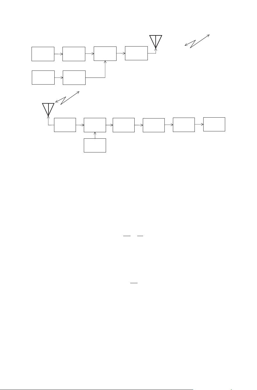
Tx Antenna
Rx Antenna
(EM Wave)
DESTINATION
WIRELESS LINK
SOURCE
Fig. 1.1 Depiction of the wireless communications problem. Tx is transmitter; EM is electro-
magnetic; Rx is receiver; Source is the place of transmission; Destination is the place of reception


剩余261页未读,继续阅读
2019-02-26 上传
2021-02-08 上传
160 浏览量
2018-12-28 上传
2019-11-15 上传
137 浏览量
317 浏览量
266 浏览量

denkywu
- 粉丝: 144
 我的内容管理
展开
我的内容管理
展开


最新资源
- 易二维码签到系统:会议活动签到解决方案
- Ceres库与SDK集成指南:C++环境配置及测试程序
- 深入理解Servlet与JSP技术应用与源码分析
- 初学者指南:掌握VC摄像头抓图源代码实现
- Java实现头像剪裁与上传的camera.swf组件
- FileTime 2013汉化版:单文件修改文件时间的利器
- 波斯语话语项目:实现discourse-persian配置指南
- MP4视频文件数据恢复工具介绍
- 微信与支付宝支付功能封装工具类介绍
- 深入浅出HOOK编程技术与应用
- Jettison 1.0.1源码与Jar包免费下载
- JavaCSV.jar: 解析CSV文档的Java必备工具
- Django音乐网站项目开发指南
- 功能全面的FTP客户端软件FlashFXP_3.6.0.1240_SC发布
- 利用卷积神经网络在Torch 7中实现声学事件检测研究
- 精选网站设计公司官网模板推荐
