
TLE7270-2
Pin Configuration
Data Sheet 4 Rev. 1.01, 2009-07-23
3 Pin Configuration
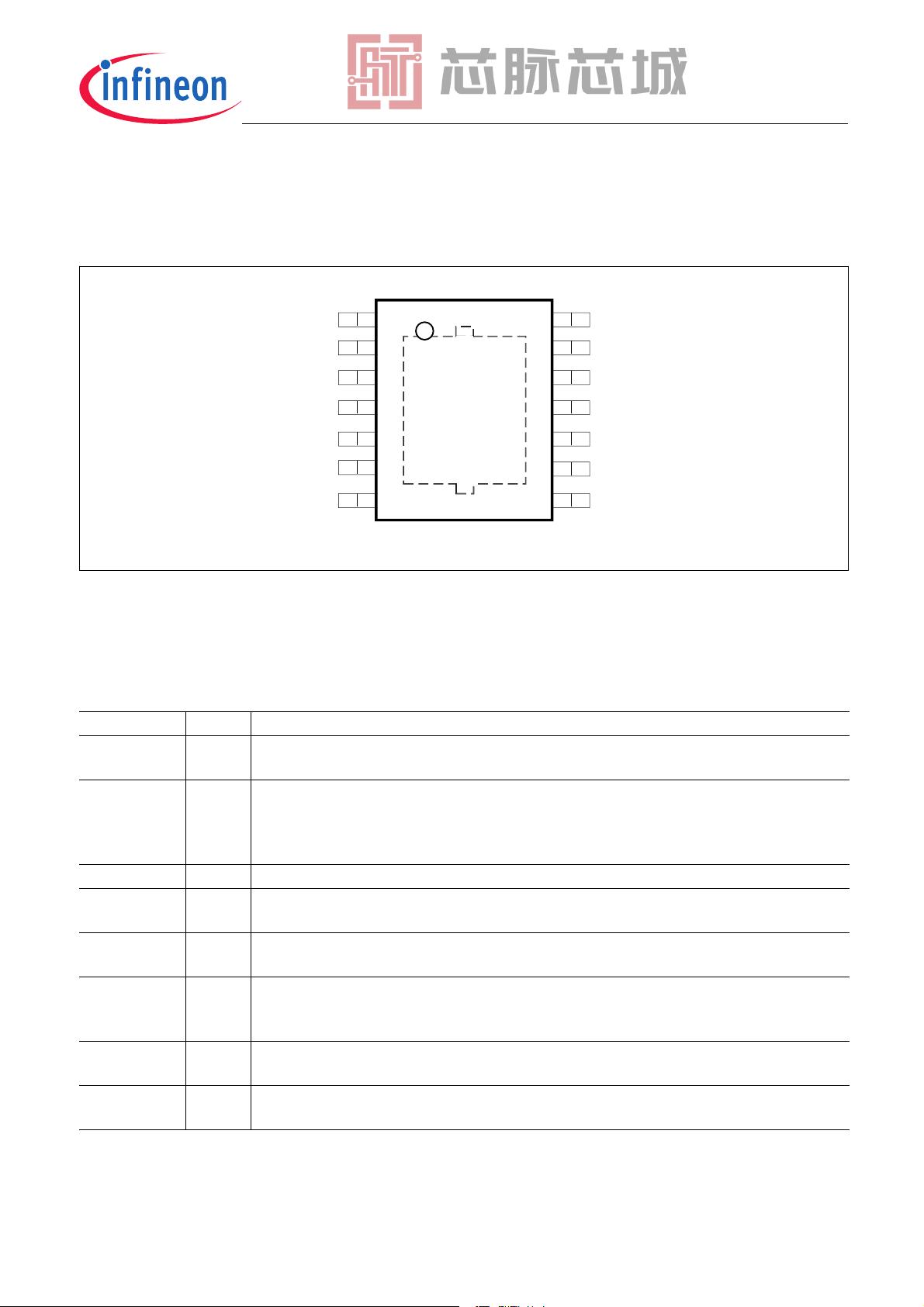
3.1 Pin Assignment PG-SSOP-14 Exposed Pad
Figure 2 Pin Configuration (top view)
3.2 Pin Definitions and Functions PG-SSOP-14 Exposed Pad
Pin No. Symbol Function
1,3,5,7 n.c. non connected
can be open or connected to GND
2ROReset Output
open collector output with integrated pull-up resistor;
optional external pull-up resistor of ≥ 10 kΩ to pin Q;
leave open if reset function not needed
4GNDGround
6DTDelay Timing
connect to GND or Q to choose the Power On Reset Delay Time
8,10,11,12,14 n.c. non connected
can be open or connected to GND
9QOutput
block to ground with a capacitor close to the IC terminals, respecting the values given
for its capacitance and ESR in “Functional Range” on Page 6
13 I Input
block to ground directly at the IC with a ceramic capacitor
Pad – Exposed Pad
connect to GND and heatsink area
QF
QF
4
QF
QF
QF
,
QF
QF
'7
QF
*1'
QF
52
7/(B3,1&21),*B6623
69*
剩余19页未读,继续阅读

芯脉芯城
- 粉丝: 3
- 资源: 4030
 我的内容管理
收起
我的内容管理
收起
- 我的资源
快来上传第一个资源
 我的收益 登录查看自己的收益
 我的积分
登录查看自己的积分
我的积分
登录查看自己的积分
 我的C币
登录后查看C币余额
我的C币
登录后查看C币余额
 我的收藏
我的收藏  我的下载
我的下载  下载帮助
下载帮助

会员权益专享


最新资源
- Simulink在电机控制仿真中的应用
- 电子警察:功能、结构与抓拍原理详解
- TESSY 4.1 英文用户手册:Razorcat Development GmbH
- 5V12V直流稳压电源设计及其实现
- 江西建工四建来宾市消防支队高支模施工方案
- 三维建模教程:创建足球模型
- 宏福苑南二区公寓楼施工组织设计
- 福建外运集团信息化建设技术方案:网络与业务平台设计
- 打造理想工作环境:详尽的6S推行指南
- 阿里巴巴数据中台建设与实践
- 欧姆龙CP1H PLC操作手册:SYSMACCP系列详解
- 中国移动统一DPI设备技术规范:LTE数据合成服务器关键功能详解
- 高校竞赛信息管理系统:软件设计与体系详解
- 面向对象设计:准则、启发规则与系统分解
- 程序设计基础与算法解析
- 算法与程序设计基础概览
资源上传下载、课程学习等过程中有任何疑问或建议,欢迎提出宝贵意见哦~我们会及时处理!
点击此处反馈


