TLE4699E 英飞凌芯片 INFINEON 中文版规格书手册
需积分: 5 188 浏览量
更新于2023-11-24
收藏 1.42MB PDF 举报
TLE4699E 英飞凌芯片 INFINEON 中文版规格书手册.pdf是一份关于汽车电源的数据手册,于2010年11月30日首次发布。该手册总共包括5个部分,分别是概述、方框图、引脚配置、引脚分配和功能定义。其中,TLE4699E是一款低压降线性稳压器,输出电压为5V。手册中详细介绍了TLE4699E的性能和功能特点,以及引脚的配置和功能定义。手册的目的是为使用者提供关于TLE4699E稳压器的详尽信息,方便对其进行合理的应用和设计。
Data Sheet 6 Rev. 1.0, 2010-11-30
TLE4699
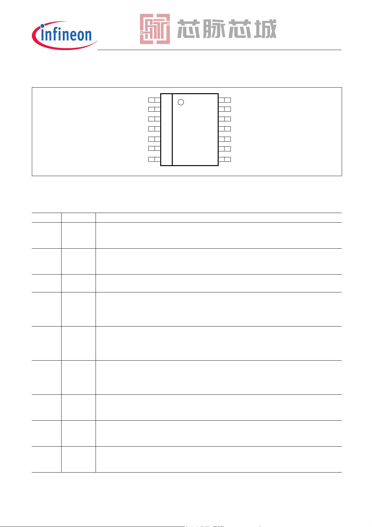
Pin Configuration
13 I Regulator Input and IC Supply
for compensating line influences, a capacitor to GND close to the IC pin is recommended.
14 SI Sense Input
Connect the voltage rail to be monitored;
Connect to Q if the sense comparator is not needed.
Pin Symbol Function
剩余30页未读,继续阅读
2023-07-07 上传
2023-07-07 上传
2023-07-07 上传
2023-07-06 上传
2023-07-07 上传
2023-07-07 上传
2023-07-07 上传
2023-07-17 上传

芯脉芯城
- 粉丝: 4
- 资源: 4030
 我的内容管理
展开
我的内容管理
展开


最新资源
- 示例:学习使用Python和Qt创建桌面应用
- FRCoreDataOperation:NSOperation子类的集合,可简化在后台线程中使用NSManagedObjects
- Ad-Blocker Pro-crx插件
- reading-notes:阅读代码研究员的笔记
- playgame-开源
- dns_query.rar_Windows编程_Unix_Linux_
- Karma-crx插件
- PolyU_beamer_theme:理大和COM的非官方Beamer主题
- 浪潮项目
- Mobile-Detect-2.6.4.zip_WEB开发_PHP_
- InfoNotary Browser Signer-crx插件
- klayout:KLayout主要来源
- OpenSource_Contributor_Guide:关于如何为开源项目做出贡献的简短而甜蜜的指南
- FlipDotCompendium:与Luminator Mega Max 3000系列标志有关的信息,在98x16正面标志和90x7侧面标志上有详细说明
- cs42l73.rar_单片机开发_Unix_Linux_
- 妮娜(Nina):一组Shorcuts在Revit中可以更快地工作
