A4962:汽车级三相无刷直流电机控制器
需积分: 12 57 浏览量
更新于2024-07-16
收藏 664KB PDF 举报
A4962-Datasheet.pdf
本文介绍的A4962KLPTR-T是一款专为汽车应用设计的三相无传感器、无刷直流(BLDC)电机控制器,它可以与外部的互补P沟道和N沟道功率MOSFET配合使用。这款控制器的设计目标是提供高效、可靠的电机驱动方案,尤其适合在汽车环境中的各种工况下工作。
A4962的主要特性在于其传感器less设计,即无需独立的位置传感器就能实现电机的相位切换。它通过监测电机的反电动势(back-EMF或bemf)来确定相位切换的时机,这种称为块换向(trapezoidal drive)的方法简化了系统复杂性并提高了效率。这种传感器less启动策略使得A4962能够适应更广泛的电机和负载组合,增强了其在不同工作条件下的适用性。
控制器可以独立工作,直接与电子控制单元(ECU)通信,也可以与本地微控制器(MCU)集成,以构建紧凑的控制系统。A4962支持多种操作模式,包括占空比(电压)控制、电流(扭矩限制)控制以及闭环速度控制。用户可以通过SPI兼容的串行接口更改操作模式和控制参数,提供了高度的灵活性和可配置性。
在性能方面,A4962能够覆盖极广的电机转速范围,从低于100rpm到超过30,000rpm,具体取决于供电电压和电机的性能。这样的宽速范围使其适用于各种不同的汽车应用,如空调系统、散热风扇、水泵以及其他需要精确控制电机转速的场合。
此外,A4962还内置了专门的电路,确保其在广泛的速度范围内稳定运行。这些功能包括对电机速度的精确控制,以及在不同工况下的保护机制,如过流、过热和欠压保护,以确保设备的可靠性和安全性。
A4962KLPTR-T是一款高性能、多功能的三相无刷直流电机控制器,特别适合于要求严苛的汽车环境。其无传感器技术、宽转速范围以及灵活的操作模式使其成为汽车电子系统中理想的选择,可以有效提高系统的效率和稳定性。

Sensorless BLDC Controller
A4962
8
Allegro MicroSystems, LLC
115 Northeast Cutoff
Worcester, Massachusetts 01615-0036 U.S.A.
1.508.853.5000; www.allegromicro.com
Characteristics Symbol Test Conditions Min. Typ. Max. Unit
Start Duty Cycle D
ST
Default power-up value 47.5 50 52.5 %
Motor Run Parameters
Phase Advance (in electrical degrees) θ
ADV
Default power-up value 14 15 16 º
Position Control Proportional Gain K
CP
Default power-up value – 1 – –
Position Control Integral Gain K
CI
Default power-up value – 1 – –
Speed Control Proportional Gain K
SP
Default power-up value – 1 – –
Speed Control Integral Gain K
SI
Default power-up value – 1 – –
Maximum Control Speed f
MX
Default power-up value 3112.9 3276.7 3440.5 Hz
Speed Error Ef
CCMX
–5 – 5 %
Current Limiting
Current Limit Threshold Voltage
Range
V
ILIM
V
ILIM
= V
CSP
– V
CSM
. 12.5 – 200 mV
Current Limit Threshold Voltage V
ILIM
Default power-up value – 200 – mV
Current Limit Threshold Voltage Error
7
E
ILIM
V
IL
= 1111 –5% – 5% %FS
Fixed Off Time t
PW
Default power-up value 47.9 50.4 52.9 µs
Blank Time t
BL
Default power-up value 3.04 3.2 3.36 µs
Protection
VBB Undervoltage Lockout
V
BBON
V
BB
rising 4.2 4.4 4.6 V
V
BBOFF
V
BB
falling 3.8 4.0 4.2 V
VBB POR Voltage V
BBR
V
BB
falling – 3.2 3.5 V
VBB POR Voltage Hysteresis V
BBRHys
– 100 – mV
VDS Threshold V
DST
Default power-up value 1325 1550 1705 mV
VDS Threshold Max – High Side V
DST
V
BB
≥ 7 V – – 1705 mV
6 V ≤ V
BB
< 7 V – – 1000 mV
5.5 V ≤ V
BB
< 6 V – – 400 mV
VDS Threshold Max – Low Side V
DST
V
BB
≥ 4.2 V – – 1705 mV
VDS Threshold Offset
4,5
V
DSTO
V
DST
≥ 1 V – ±100 – mV
V
DST
≤ 1 V –150 ±50 150 mV
Temperature Warning Threshold T
JWH
Temperature increasing 125 135 150 ºC
Temperature Warning Hysteresis T
JWHhys
– 15 – ºC
Over-temperature Threshold T
JF
Temperature increasing 170 175 180 ºC
Over-temperature Hysteresis T
JHyst
Recovery = T
JF
– T
JHyst
– 15 – ºC
1
Function is correct but parameters are not guaranteed above or below the general limits (6-28 V).
2
For input and output current specications, negative current is dened as coming out of (sourcing) the specied device terminal.
3
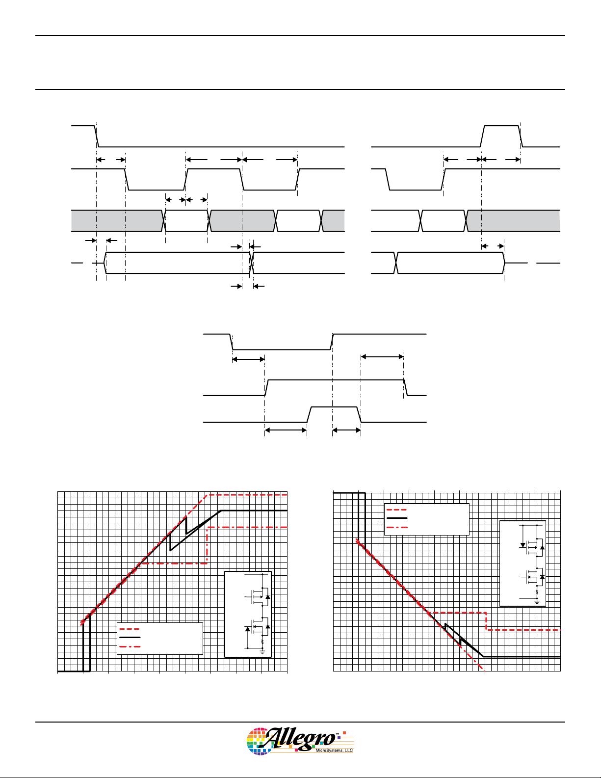
See Figure 2 for gate drive output timing.
4
As V
SX
decreases, high-side fault occurs if (V
BAT
- V
SX
) > (V
DST
+ V
DSTO
)
5
As V
SX
increases, low-side fault occurs if (V
SX
) > (V
DST
+ V
DSTO
)
6
See Figures 4 & 5 for V
DS
monitor timing.
7
Current limit threshold voltage error is the difference between the target threshold voltage and the actual threshold voltage, referred to maximum full scale (100%) current:
E
ILIM
= 100 × (V
ILIMActual
– V
ILIM
)/200%. (V
ILIM
in mV)
ELECTRICAL CHARACTERISTICS (continued): valid at T
A
= 25°C, V
BB
= 4.2 V to 28 V (unless noted otherwise)
剩余41页未读,继续阅读
2020-04-08 上传
2018-10-11 上传
2020-04-08 上传
2020-04-07 上传
2021-05-20 上传
2020-04-07 上传
2020-04-07 上传
2020-04-07 上传

dldzjsyyy
- 粉丝: 176
- 资源: 18
 我的内容管理
展开
我的内容管理
展开


最新资源
- 网络化
- ignite-nodejs-desafio-03
- bootstrap-swig-stylus-gulp-boilerplate:包含 Bootstrap、Swig、Stylus、Gulp 和一些基本导入的最小种子,如 Google Webfonts、FontAwesome 等
- web_app_example
- 最终项目:绘图效率和耐力
- Final-JS_Project:国际邮政服务
- 数码宝贝游戏易语言源码-易语言
- Music-App:使用HTML + CSS + Javascript制作的简单动画音乐应用程序
- my-JS-Project:这是一个JavaScript项目存储库
- VisualVM.zip
- desdevdemo:该网站用于展示2021年DES&DEV训练营参与者建造的项目
- react
- pro-javascript-ria-techniques:支持 Apress 书籍“Pro JavaScript RIA 技术”的代码清单
- kendrick-keits
- fashiondata
- csb_js_file_conversion:用于Codesandbox的Javascript文件上传器skelton
