JESD204B调试指南:关键原理与实战应用
需积分: 5 134 浏览量
更新于2024-06-16
2
收藏 2.21MB PDF 举报
JESD204B调试手册是一份专注于高速信号传输接口JESD204B的专业文档,该接口在现代AD/DA转换器等高速电子元件中扮演了重要角色,其传输速率和容量性能对器件性能评价至关重要。调试和验证JESD204B已经成为研发过程中不可或缺的一部分,它直接关系到项目进度,因此对于研发工程师和现场支持人员来说,理解并掌握JESD204B的基本原理、调试方法是基本技能。
文档内容分为多个部分,首先介绍了JESD204B的概述,包括其广泛的应用领域和作为衡量器件性能的重要指标。接着详细解析了JESD204B的层次结构,包括关键参数描述和TX/RX功能模型,这些是理解接口工作原理的基础。
调试步骤是文档的核心部分,涉及键链(Establishment)阶段,包括码组同步及其问题排查,确保信号的正确初始化。作者还特别强调了初始帧同步(InitialFrameAlignment)和初始lane同步(ILAS),这两个步骤对于确保数据传输的准确性至关重要。此外,确定性延迟(DeterministicLatency)的实现,特别是通过RBD(Relative Burst Delay)设置来控制延迟,是调试中的关键环节。
文档还涵盖了JESD204B告警处理,区分了非标准和标准告警类型,帮助用户识别和解决潜在问题。附录中包含了相关的图表,如JESD204B的适用场景示意图、逻辑分层图以及数据映射说明,直观地展示了接口的工作方式。
这份手册提供了全面的JESD204B调试指南,不仅阐述了理论知识,还通过实例演示了如何进行实际操作,对提高工程师在高速信号传输接口上的实践能力大有裨益。无论是初学者还是经验丰富的从业者,都能从中受益匪浅。
ZHCA737
4 JESD 204B
调试手册
上述的四种模式是两个对象的几种组合,一个是数据转换器的个数,另外一个是对应的link的个数。
数据转换器就是对应的I/Q的数据组,例如我们无线系统中都是采用complex数据有16bits 的I 也有
16bits的Q,那么对应的转换器就是2,就类似I数据需要一个转换器来完成,Q数据需要一个转换器来
完成(注意这里的转换器的个数和我们通常所说的物理的ADC/DAC数据有区别,可以抽象为一个吞吐
数据器件)。 通常情况下我们转换器的个数都是多个(多通道),这些转换器的数据可以一起来建链
称之为单link也可以分组建链称之为多link。 所以下面将于常用的Multiple converters in the same device
to a multi-lane link来说明。
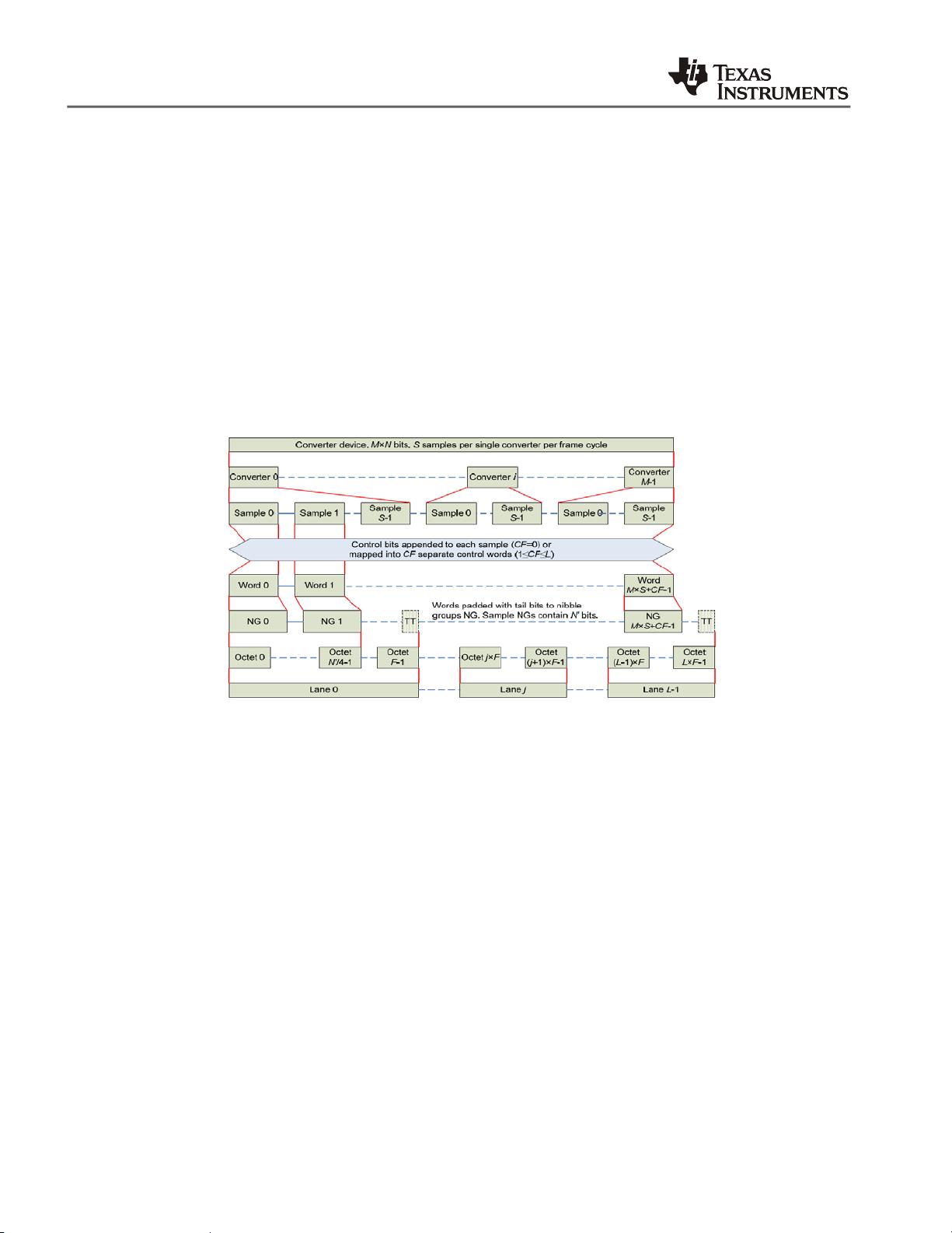
在传输层映射过程中会用到几个参数:
• CF: Number of control words per frame clock period per link.
• CS: Number of control bits per conversion sample.
• NG: Nibble Group(group of half octets).
这三个参数会影响到映射的过程,但实际的过程中往往没有这些控制字,同时也不需要插入nibble数
据,所以会比较简单。 这些数据的映射过程和排列过程会体现在JESD的LMFS 等配置中,一般数据
手册中都会给出我们支持的模式说明。
Figure 2 204B 的传输层数据映射说明
参考上图,传输层的动作过程可以描述如下:
• Maps the data octets frames consisting of multiple octets
• Adds optional control bits to samples if needed
– Control bits can be used to communicate status information, mark an inactive converter on the
link or control receiver operation
• Distinguishes the possible combinations of device/links/lanes/etc.
– Single converter connected to single lane link
– Single converter connected to multiple lanes link
– Multiple converters in a converter device connected to a single lane link
– Multiple converters in a converter device connected to multiple lanes link
2. 加扰(Scrambler)
加扰的主要目的是去除数据相关性例如各个帧同时发送相同的数据,从而减小造成的系统干扰和
减小电磁兼容性问题。 按照实际的运用可以选择加扰或者不加扰。
3.
链接层(Link layer)
剩余18页未读,继续阅读
4507 浏览量
229 浏览量
点击了解资源详情
2024-05-31 上传
195 浏览量
135 浏览量
380 浏览量
4507 浏览量

大佬们多指教
- 粉丝: 0
- 资源: 5
 我的内容管理
展开
我的内容管理
展开


最新资源
- 2009年java最新面试题
- Graphical Models, Exponential Families, and Variational Inference
- 计算机外文 计算机专业
- C# 如何判断一个Byte数组中是否存在某些连续的数据).txt
- unix常用命令有助于日常工作的小贴士
- C# 的类型转换.doc
- 华为笔试面试指南有兴趣的可以好好看
- service 天气预报
- 城市生活垃圾逆向物流网络优化设计
- C#编码规范,共享参考
- Ext 的中文手册PDF
- A Multiresolution Image Segmentation Technique Based on Pyramidal Segmentation and Fuzzy Clustering
- 图书管理系统SQL数据库
- C#完全手册.pdf
- 工作流原理及实例说明
- java从基础到应用编程经验
