磁铁优化的无轴承同步磁阻电机设计
需积分: 10 77 浏览量
更新于2024-09-08
收藏 1.29MB PDF 举报
"这篇论文是关于优化无轴承同步磁阻电机(Bearingless Synchronous Reluctance Motors,BSynRMs)设计的研究,通过引入铁氧体磁铁的新颖转子结构来解决传统BSynRMs低扭矩密度和功率因数的问题。作者首先介绍了BSynRMs的基本结构和工作原理,并推导了扭矩和悬浮力的数学模型。其次,利用有限元分析方法对磁障层、转子肋宽和永磁体参数进行优化,以提高显著极比和d轴与q轴电感的差异。最后,对比优化后的电机与传统BSynRM在扭矩、悬浮力和功率因数方面的性能,结果显示优化电机在最佳角度下扭矩密度和功率因数分别提高了54.4%和56.3%,但平均悬浮力因磁饱和降低了约15.7%。优化电机的实验验证了其具有良好的悬浮和速度调节性能。"
本文是《应用超导技术》期刊2018年4月第28卷第3期的一篇文章,由丁海飞、朱黄秋和华一舟共同撰写。文章的核心内容围绕着如何改进无轴承同步磁阻电机的性能展开。传统BSynRMs的主要缺点是扭矩密度低和功率因数小,这限制了它们在实际应用中的效能。为此,研究者提出了一种新的设计方案,即在转子结构中加入铁氧体磁铁。
在理论分析部分,研究者详细阐述了BSynRMs的基础构造和运行原理,同时建立了扭矩和悬浮力的数学模型,这为后续的参数优化提供了理论依据。接下来,借助有限元分析工具,对电机的关键参数进行了精细化优化。具体来说,优化目标是增加磁障层的厚度、转子肋的宽度以及永磁体的配置,以增强磁路的不对称性,从而提升电机的磁极比和d、q轴电感的差异。
通过比较优化电机与传统BSynRM的性能,发现优化后的电机在最佳工况下扭矩密度提升了54.4%,功率因数提高了56.3%,这意味着电机在保持相同体积或重量的情况下,能提供更高的动力输出和能效转换。然而,这也带来了一个负面影响,即平均悬浮力减少了15.7%,这可能是由于磁饱和效应导致的。尽管如此,优化设计仍然确保了电机具有良好的悬浮稳定性和速度控制性能,这对无轴承电机的应用至关重要。
这项工作为无轴承同步磁阻电机的设计提供了新的思路,通过优化关键参数实现了扭矩密度和功率因数的显著提升,同时对悬浮力的影响也进行了深入探讨。这一研究成果对于推动BSynRMs在高效能驱动系统、航空航天以及精密机械设备等领域的应用具有重要的理论价值和实践意义。
IEEE TRANSACTIONS ON APPLIED SUPERCONDUCTIVITY, VOL. 28, NO. 3, APRIL 2018 5202905
Optimization Design of Bearingless Synchronous
Reluctance Motor
Haifei Ding , Huangqiu Zhu , and Yizhou Hua
Abstract—In order to overcome common drawbacks of the low
torque density and power factor for conventional bearingless syn-
chronous reluctance motors (BSynRMs), a novel BSynRM rotor
structure with ferrite magnets is designed in this paper. First, the
basic structure and operation principle of the BSynRM are in-
troduced, and the mathematical models of torque and suspension
forces are deduced. Second, based on the finite element analysis
method, the parameters of flux barriers layer, rotor rib width, and
permanent magnets are optimized to increase the salient pole ratio
and the difference between d and q axes inductance. Third, the
performance of torque, suspension forces, and power factor for the
optimized motor is compared with that of the traditional BSynRM.
The research results show that the torque density and power fac-
tor increase about 54.4% and 56.3% respectively at optimal angle,
whereas the average suspension force decreases about 15.7% owing
to magnetic saturation. The optimized motor is validated to have
good suspension and speed regulation performance.
Index Terms—Bearingless synchronous reluctance motor
(BSynRM), optimization design, power factor, torque density.
I. INTRODUCTION
T
HE normal operation of a traditional motor cannot be sep-
arated from bearing support. But some problems, such as
friction and wear, mechanical vibration, and noise, may be pro-
duced by bearings during the operation of traditional motors. In
the middle and later period of twentieth century, the magnetic
bearings solved problems above effectively [1]. At the same
time, the magnetic bearings may also cause problems, such as
longer axial length, relatively complex structure and control, as
well as higher costs. So the motors supported by magnetic bear-
ings are difficult to realize high speed operation, which limits
their scope of application.
The bearingless synchronous reluctance motors (BSynRMs)
inherit the merits of magnetic bearings and synchronous reluc-
tance motors (SynRMs). According to the similarity in structure
between the magnetic bearings and SynRMs, the windings used
to produce the radial suspension force in magnetic bearings are
Manuscript received August 26, 2017; accepted January 7, 2018. Date of pub-
lication January 16, 2018; date of current version January 29, 2018. This work
was supported in part by the Key Research and Development Project of Jiangsu
Province (BE2016150), in part by the Priority Academic Program Development
of Jiangsu Higher Education Institutions (2014), and in part by the Gradu-
ate Student Practice Innovation Project of Jiangsu Province (SJLX16_0427).
(Corresponding author: Huangqiu Zhu.)
The authors are with the School of Electrical and Information Engineer-
ing, Jiangsu University, Zhenjiang 212013, China (e-mail: zhuhuangqiu@
ujs.edu.cn).
Color versions of one or more of the figures in this paper are available online
at http://ieeexplore.ieee.org.
Digital Object Identifier 10.1109/TASC.2018.2793192
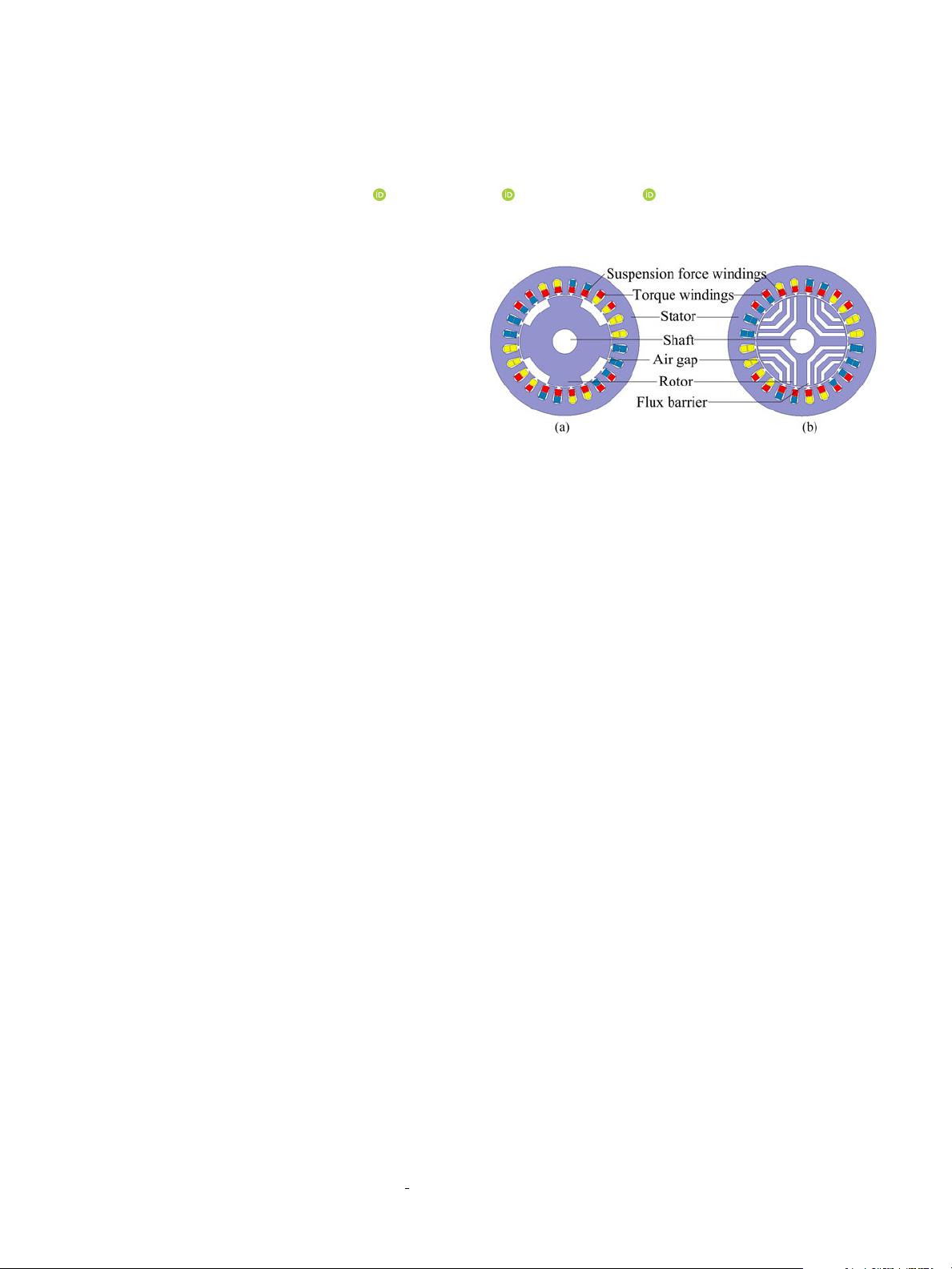
Fig. 1. Cross sections of BSynRMs with different rotor. (a) Salient pole rotor.
(b) Flux barrier rotor.
superimposed in the stator windings of SynRMs. The BSyn-
RMs, thus, have the advantages of simpler structure, higher
critical speed, and smaller volume [2].
Common drawbacks of the conventional BSynRM with
salient pole rotor are the low torque density and power fac-
tor, which can be overcome by increasing the salient pole ratio
and the difference between d- and q-axis inductance. A new
BSynRM with multi-flux barriers rotor can produce torque and
suspension forces effectively, but the power factor is not sig-
nificantly improved [3]. In general SynRMs, rotor structures
with auxiliary permanent magnets have been reported to have
good torque and power factor characteristics [4], [5]. In this
paper, the structure and working principle of the BSynRM are
introduced, and the mathematical models of radial suspension
forces and torque are established. Then, the optimal design of
the BSynRM is carried out based on the simple variable method.
The effects of different rotor dimensions, including flux barriers
layer, rotor rib width and permanent magnets, are studied using
the finite element analysis method (FEM). The good suspension
and torque performance of the optimized motor can be gotten
by means of vector control strategy.
II. M
OTOR TOPOLOGY AND OPERATING PRINCIPLE
A. Topology of the BSynRM
The types of BSynRM rotor include salient pole rotor and
flux barriers rotor, as shown in Fig. 1. The power factor and
torque density of the BSynRM with the latter rotor have been
improved compared with the former. The stator windings of the
BSynRM are divided into outer torque windings and inner sus-
pension force windings. Fig. 2 shows that the rotor of BSynRM
is supported by a self-aligning ball bearing, which makes the
1051-8223 © 2018 IEEE. Personal use is permitted, but republication/redistribution requires IEEE permission.
See http://www.ieee.org/publications
standards/publications/rights/index.html for more information.
下载后可阅读完整内容,剩余4页未读,立即下载
点击了解资源详情
点击了解资源详情
点击了解资源详情
2021-02-13 上传
2021-02-09 上传
2021-02-13 上传
110 浏览量
157 浏览量
2021-04-23 上传
2021-02-07 上传

dinghaif
- 粉丝: 0
 我的内容管理
展开
我的内容管理
展开


最新资源
- 小学水墨风学校网站模板设计
- 深入理解线程池的实现原理与应用
- MSP430编程代码集锦:实用例程源码分享
- 绿色大图幻灯商务响应式企业网站开发源码包
- 深入理解CSS与Web标准的专业解决方案
- Qt/C++集成Google拼音输入法演示Demo
- Apache Hive 0.13.1 版本安装包详解
- 百度地图范围标注技术及应用
- 打造个性化的Windows 8锁屏体验
- Atlantis移动应用开发深度解析
- ASP.NET实验教程:源代码详细解析与实践
- 2012年工业观察杂志完整版
- 全国综合缴费营业厅系统11.5:一站式缴费与运营管理解决方案
- JAVA原生实现HTTP请求的简易指南
- 便携PDF浏览器:随时随地快速查看文档
- VTF格式图片编辑工具:深入起源引擎贴图修改
