没有合适的资源?快使用搜索试试~ 我知道了~
首页达芬奇(DaVinci)处理器——TMS320DM355
达芬奇(DaVinci)处理器——TMS320DM355
4星 · 超过85%的资源 需积分: 14 26 下载量 5 浏览量
更新于2023-07-14
评论 1
收藏 1.28MB PDF 举报
2007 年9 月份左右的时候,德州仪器(TI)推出针对便携式高清(HD)视频产品市场的最新 达芬奇(DaVinci)处理器——TMS320DM355,其具备ARM主机控制与全套开发工具。该产品不 仅能够实现高清视频(MPEG-4-JPEG)性能,而且其电池使用寿命也是当前其它高清产品的两 倍。 DM355 处理器由集成的视频处理子系统、MPEG-4-JPEG 协处理器(MJCP)、ARM926EJ-S 内核以及多种外设组成,针对数码相机、IP摄像机、数码相框以及婴儿视频监护器等应用。
资源详情
资源评论
资源推荐
www.ti.com
PRODUCT PREVIEW
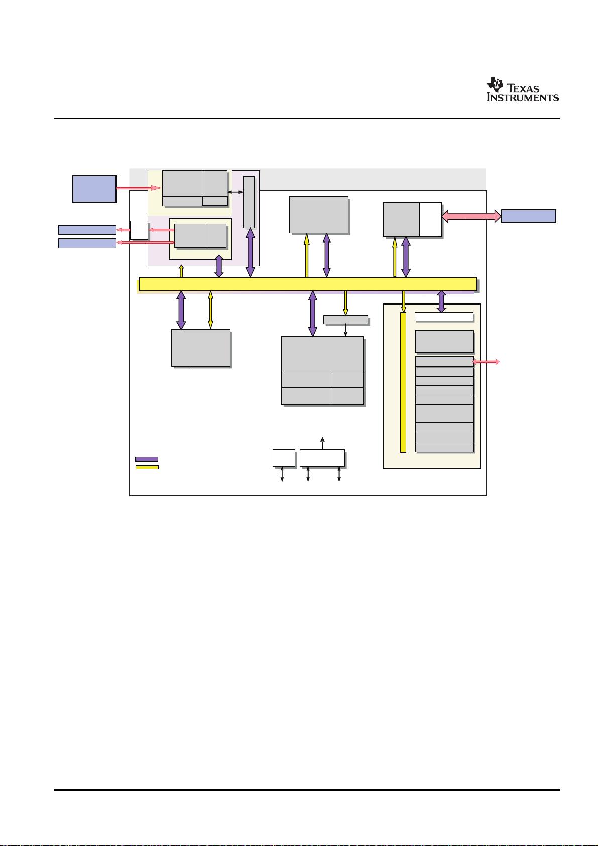
1 TMS320DM355 Digital Media System-on-Chip (DMSoC)
1.1 Features
TMS320DM355
Digital Media System-on-Chip (DMSoC)
SPRS463 – SEPTEMBER 2007
encoder
• High-Performance Digital Media
System-on-Chip • External Memory Interfaces (EMIFs)
– 216- and 270-MHz ARM926EJ-S Clock Rate – DDR2 and mDDR SDRAM 16-bit wide EMIF
With 256 MByte Address Space (1.8-V I/O)
– Fully Software-Compatible With ARM9
– Asynchronous16-/8-bit Wide EMIF (AEMIF)
• ARM926EJ-S Core
• Flash Memory Interfaces
– Support for 32-Bit and 16-Bit (Thumb Mode)
– NAND (8-/16-bit Wide Data)
Instruction Sets
– OneNAND(16-bit Wide Data)
– DSP Instruction Extensions and Single
Cycle MAC
• Flash Card Interfaces
– ARM Jazelle Technology
– Two Multimedia Card (MMC) / Secure
– EmbeddedICE-RT Logic for Real-Time Digital (SD/SDIO)
Debug
– SmartMedia
• ARM9 Memory Architecture
• Enhanced Direct-Memory-Access (EDMA)
– 16K-Byte Instruction Cache Controller (64 Independent Channels)
– 8K-Byte Data Cache
• USB Port with Integrated 2.0 High-Speed PHY
that Supports
– 32K-Byte RAM
– USB 2.0 Full and High-Speed Device
– 8K-Byte ROM
– USB 2.0 Low, Full, and High-Speed Host
– Little Endian
• Three 64-Bit General-Purpose Timers (each
• Video Processing Subsystem
configurable as two 32-bit timers)
– Front End Provides:
• One 64-Bit Watch Dog Timer
• Hardware IPIPE for Real-Time Image
Processing • Three UARTs (One fast UART with RTS and
CTS Flow Control)
• CCD and CMOS Imager Interface
• Three Serial Port Interfaces (SPI) each with
• 14-Bit Parallel AFE (Analog Front End)
two Chip-Selects
Interface Up to 75MHz
• One Master/Slave Inter-Integrated Circuit
• Glueless Interface to Common Video
(I
2
C) Bus™
Decoders
• BT.601/BT.656 Digital YCbCr 4:2:2 • Two Audio Serial Port (ASP)
(8-/16-Bit) Interface
– I2S and TDM I2S
• Histogram Module
– AC97 Audio Codec Interface
• Resize Engine
– S/PDIF via Software
– Resize Images From 1/16x to 8x
– Standard Voice Codec Interface (AIC12)
– Separate Horizontal/Vertical Control
– SPI Protocol (Master Mode Only)
– Two Simultaneous Output Paths
• Four Pulse Width Modulator (PWM) Outputs
– Back End Provides:
• Four RTO (Real Time Out) Outputs
• Hardware On-Screen Display (OSD)
• Up to 104 General-Purpose I/O (GPIO) Pins
• Composite NTSC/PAL video encoder
(Multiplexed with Other Device Functions)
output
• On-Chip ARM ROM Bootloader (RBL) to Boot
• 8-/16-bit YCC and Up to 18-Bit RGB666
From NAND Flash, MMC/SD, or UART
Digital Output
• Configurable Power-Saving Modes
• BT.601/BT.656 Digital YCbCr 4:2:2
• Crystal or External Clock Input (typically
(8-/16-Bit) Interface
24MHz or 36MHz)
• Supports digital HDTV (720p/1080i)
• Flexible PLL Clock Generators
output for connection to external
• Debug Interface Support
Please be aware that an important notice concerning availability, standard warranty, and use in critical applications of Texas
Instruments semiconductor products and disclaimers thereto appears at the end of this document.
I
2
C-bus is a trademark of Texas Instruments.
Windows is a trademark of Microsoft.
All other trademarks are the property of their respective owners.
PRODUCT PREVIEW information concerns products in the
Copyright © 2007, Texas Instruments Incorporated
formative or design phase of development. Characteristic data and
other specifications are design goals. Texas Instruments reserves
the right to change or discontinue these products without notice.
www.ti.com
PRODUCT PREVIEW
TMS320DM355
Digital Media System-on-Chip (DMSoC)
SPRS463 – SEPTEMBER 2007
– IEEE-1149.1 (JTAG) • 337-Pin Ball Grid Array (BGA) Package
Boundary-Scan-Compatible (ZCE Suffix), 0.65-mm Ball Pitch
– ETB (Embedded Trace Buffer) with
• 90nm Process Technology
4K-Bytes Trace Buffer memory
• 3.3-V and 1.8-V I/O, 1.3-V Internal
– Device Revision ID Readable by ARM
2 TMS320DM355 Digital Media System-on-Chip (DMSoC) Submit Documentation Feedback
www.ti.com
PRODUCT PREVIEW
1.2 Description
TMS320DM355
Digital Media System-on-Chip (DMSoC)
SPRS463 – SEPTEMBER 2007
The DM355 is a highly integrated, programmable platform for digital still camera, digital photo frames, IP
security cameras, 4-channel digital video recorders, video door bell application, and other low cost
portable digital video applications. Designed to offer portable video designers and manufacturers the
ability to produce affordable portable digital video solutions with high picture quality, the DM355 combines
high performance, high quality, low power consumption at a very low price point. The DM355 also enables
seamless interface to most additional external devices required for a complete digital camera
implementation. The interface is flexible enough to support various types of CCD and CMOS sensors,
signal conditioning circuits, power management, DDR/mDDR memory, SRAM, NAND, shutter, Iris and
auto-focus motor controls, etc.
The processor core is an ARM926EJ-S RISC processor. The ARM926EJ-S is a 32-bit processor core that
performs 32-bit and 16-bit instructions and processes 32-bit, 16-bit, and 8-bit data. The core uses
pipelining so that all parts of the processor and memory system can operate continuously. The ARM core
incorporates:
• A coprocessor 15 (CP15) and protection module
• Data and program Memory Management Units (MMUs) with table look-aside buffers.
• Separate 16K-byte instruction and 8K-byte data caches. Both are four-way associative with virtual
index virtual tag (VIVT).
DM355 performance is enhanced by its MPEG/JPEG co-processor. The MPEG/JPEG co-processor
performs the computational operations required for image processing; JPEG compression and MPEG1,2,4
video and imaging standards.
The device has a Video Processing Subsystem (VPSS) with two configurable video/imaging peripherals:
• A Video Processing Front-End (VPFE)
• A Video Processing Back-End (VPBE)
The VPFE port provides an interface for CCD/CMOS imager modules and video decoders. The VPBE
provides hardware On Screen Display (OSD) support and composite NTSC/PAL and digital LCD output.
The DM355 peripheral set includes:
• An inter-integrated circuit (I2C) Bus interface
• Two audio serial ports (ASP)
• Three 64-bit general-purpose timers each configurable as two independent 32-bit timers
• A 64-bit watchdog timer
• Up to 104-pins of general-purpose input/output (GPIO) with programmable interrupt/event generation
modes, multiplexed with other peripherals
• Three UARTs with hardware handshaking support on one UART
• Three serial port Interfaces (SPI)
• Four pulse width modulator (PWM) peripherals
• Four real time out (RTO) outputs
• Two Multi-Media Card / Secure Digital (MMC/SD) interfaces
• A USB 2.0 full and high-speed device and host interface
• Two external memory interfaces:
– An asynchronous external memory interface (AEMIF) for slower memories/peripherals such as
NAND and OneNAND,
– A high speed synchronous memory interface for DDR2/mDDR.
For software development support the has a complete set of ARM development tools which include: C
compilers, assembly optimizers to simplify programming and scheduling, and a Windows™ debugger
interface for visibility into source code execution.
Submit Documentation Feedback TMS320DM355 Digital Media System-on-Chip (DMSoC) 3
www.ti.com
PRODUCT PREVIEW
1.3 Functional Block Diagram
Peripherals
64bitDMA/DataBus
JTAG
24MHz 27MHz
(optional)
CCD/
CMOS
Module
DDR2/MDDR16
CLOCK
PLL
CLOCKctrl
PLLs
JTA
JTAG
I/F
Clocks
ARM
z )
ARM926EJ-S_Z8
I-
cach
e
16 K
B
l-cache
16KB
B
RA
M
32 K
B
RAM
32KB
B
D-
cach
e
8K
D-cache
8KB
RO
M
8 K
ROM
8KB
CCD
C
CCDC
3A
3A
DMA / Dataandconfigurationbus
DMA/Dataandconfigurationbus
DDR
MH
z )
DDR
controller
DL
DLL/
PHY
16bit
32bitConfigurationBus
IPIP
E
IPIPE
VPBE
Vide
o
Encod
er
Video
Encoder
10b
DAC
OS
D
OSD
er
c
ARM
ARMINTC
Enhanced
channels
3PCC /TC
(100 MHz
EnhancedDMA
64channels
Compositevideo
DigitalRGB/YUV
Nand /
Nand/SM/
Async/OneNand
(EMIF2.3)
USB 2 .0
USB2.0PHY
Speaker
microphone
LD /
ASP (2x)
LD/CM
B
ufferLogic
VPSS
MMC/SD(x2)
SPII/F(x3)
UART (x3)
I2C
Timer/
WDT (x4-64)
GIO
PWM(x4)
RTO
VPFE
Enhanced
channels
3PCC /TC
(100 MHz
MPEG/JPEG
Co-processor
TMS320DM355
Digital Media System-on-Chip (DMSoC)
SPRS463 – SEPTEMBER 2007
Figure 1-1 shows the functional block diagram of the DM355 device.
Figure 1-1. Functional Block Diagram
TMS320DM355 Digital Media System-on-Chip (DMSoC)4 Submit Documentation Feedback
www.ti.com
PRODUCT PREVIEW
Contents
TMS320DM355
Digital Media System-on-Chip (DMSoC)
SPRS463 – SEPTEMBER 2007
4.1 Absolute Maximum Ratings Over Operating Case
1 TMS320DM355 Digital Media System-on-Chip
Temperature Range
(DMSoC) ................................................... 1
(Unless Otherwise Noted) .......................... 90
1.1 Features .............................................. 1
4.2 Recommended Operating Conditions ............... 91
1.2 Description ............................................ 3
4.3 Electrical Characteristics Over Recommended
1.3 Functional Block Diagram ............................ 4
Ranges of Supply Voltage and Operating Case
2 Device Overview ......................................... 6
Temperature (Unless Otherwise Noted) ............ 92
2.1 Device Characteristics ................................ 6
5 Peripheral Information and Electrical
Specifications ........................................... 93
2.2 Memory Map Summary ............................... 7
5.1 Parameter Information Device-Specific Information 93
2.3 Pin Assignments ...................................... 9
5.2 Recommended Clock and Control Signal Transition
2.4 Pin Functions ........................................ 13
Behavior ............................................. 95
2.5 Pin List .............................................. 36
5.3 Power Supplies ...................................... 95
2.6 Device Support ...................................... 55
5.4 Reset ................................................ 97
3 Detailed Device Description .......................... 59
5.5 Oscillators and Clocks ............................... 98
3.1 ARM Subsystem Overview .......................... 59
5.6 General-Purpose Input/Output (GPIO) ............. 103
3.2 ARM926EJ-S RISC CPU ............................ 60
5.7 External Memory Interface (EMIF) ................. 105
3.3 Memory Mapping .................................... 62
5.8 MMC/SD ........................................... 112
3.4 ARM Interrupt Controller (AINTC) ................... 63
5.9 Video Processing Sub-System (VPSS) Overview . 114
3.5 Device Clocking ..................................... 65
5.10 USB 2.0 ............................................ 127
3.6 PLL Controller (PLLC) ............................... 72
5.11 Universal Asynchronous Receiver/Transmitter
3.7 Power and Sleep Controller (PSC) .................. 76
(UART) ............................................. 129
3.8 System Control Module ............................. 76
5.12 Serial Port Interface (SPI) .......................... 131
3.9 Pin Multiplexing ...................................... 77
5.13 Inter-Integrated Circuit (I2C) ....................... 134
3.10 Device Reset ........................................ 78
5.14 Audio Serial Port (ASP) ............................ 137
3.11 Default Device Configurations ....................... 79
5.15 Timer ............................................... 144
3.12 Device Boot Modes ................................. 82
5.16 Pulse Width Modulator (PWM) ..................... 145
3.13 Power Management ................................. 84
5.17 Real Time Out (RTO) .............................. 147
3.14 64-Bit Crossbar Architecture ........................ 86
5.18 IEEE 1149.1 JTAG ................................ 148
3.15 MPEG/JPEG Overview .............................. 89
6 Mechanical Data ....................................... 151
4 Device Operating Conditions ........................ 90
6.1 Thermal Data for ZCE ............................. 151
6.1.1 Packaging Information ............................. 151
Submit Documentation Feedback Contents 5
剩余152页未读,继续阅读
lqylovejc
- 粉丝: 0
- 资源: 4
上传资源 快速赚钱
- 我的内容管理 收起
- 我的资源 快来上传第一个资源
- 我的收益 登录查看自己的收益
- 我的积分 登录查看自己的积分
- 我的C币 登录后查看C币余额
- 我的收藏
- 我的下载
- 下载帮助
会员权益专享
最新资源
- RTL8188FU-Linux-v5.7.4.2-36687.20200602.tar(20765).gz
- c++校园超市商品信息管理系统课程设计说明书(含源代码) (2).pdf
- 建筑供配电系统相关课件.pptx
- 企业管理规章制度及管理模式.doc
- vb打开摄像头.doc
- 云计算-可信计算中认证协议改进方案.pdf
- [详细完整版]单片机编程4.ppt
- c语言常用算法.pdf
- c++经典程序代码大全.pdf
- 单片机数字时钟资料.doc
- 11项目管理前沿1.0.pptx
- 基于ssm的“魅力”繁峙宣传网站的设计与实现论文.doc
- 智慧交通综合解决方案.pptx
- 建筑防潮设计-PowerPointPresentati.pptx
- SPC统计过程控制程序.pptx
- SPC统计方法基础知识.pptx
资源上传下载、课程学习等过程中有任何疑问或建议,欢迎提出宝贵意见哦~我们会及时处理!
点击此处反馈
安全验证
文档复制为VIP权益,开通VIP直接复制
信息提交成功
评论2