事件触发下模糊系统故障检测器与控制器协调设计的稳定性与优化方法
5 浏览量
更新于2024-08-26
收藏 995KB PDF 举报
本文探讨了事件触发的故障检测器与模糊系统控制器在离散时间Takagi-Sugeno模糊系统网络环境中的协调设计问题,发表于2004年的IEEE Transactions on Fuzzy Systems第26卷第4期。作者Xiaojie Su、Fengqin Xia和Ligang Wu,均为IEEE成员,以及C.L. Philip Chen,IEEE Fellow,共同提出了新颖的解决方案。
首先,针对原始的Takagi-Sugeno模糊系统,研究者着重构建了一个考虑了事件触发机制、间隔时间变化延迟和数据包丢失的新型基于网络的残差系统。通过采用逆凸技巧,建立了更为保守的基于基的稳定性条件,确保了该残差系统在具有给定的H∞性能下,能够实现均方意义下的渐近稳定。
接下来,论文提出了一种依赖于模糊规则的故障检测器和控制器的设计方法。利用变量替换策略,将这些准则转化为可求解的凸优化问题,从而简化了设计过程,并提高了系统的实用性。这种转换使得系统设计更具效率,同时保持了对系统性能的精确控制。
在事件触发机制的背景下,设计的故障检测器能有效地减少不必要的监控频率,仅在关键时刻进行状态评估,降低了网络资源的消耗。同时,模糊控制器的加入使得系统能够在不确定性环境中表现出良好的适应性和鲁棒性,保证了系统在面对网络干扰时仍能维持稳定性和准确性。
这篇研究论文为离散时间Takagi-Sugeno模糊系统在网络环境下设计高效的故障检测与控制策略提供了创新性的理论支持和实用方法,对于提升模糊控制系统在实际工业应用中的性能和可靠性具有重要意义。
2006 IEEE TRANSACTIONS ON FUZZY SYSTEMS, VOL. 26, NO. 4, AUGUST 2018
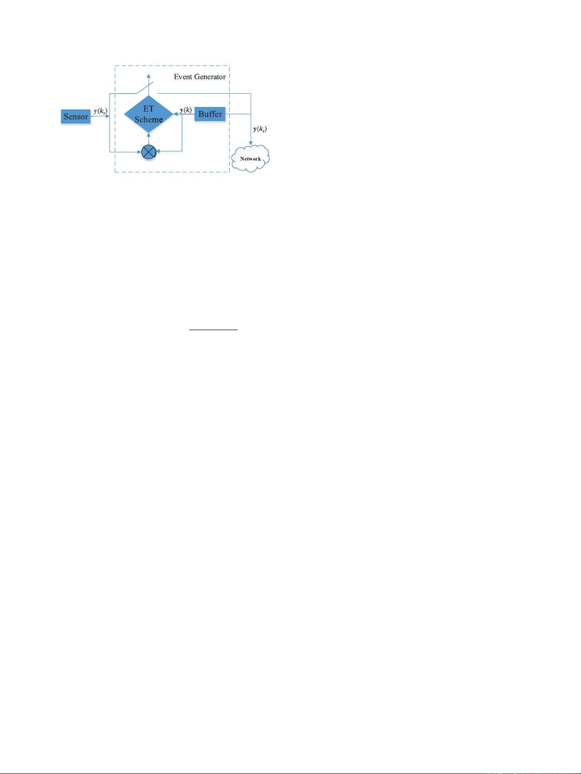
Fig. 1. Transmitting-data generator.
the noise input signal, respectively, which are considered
to belong to
2
[0, ∞),fori ∈ S {1, 2,...,r}, r is the
number of IF–THEN rules; μ
i1
,...,μ
ip
are the fuzzy sets;
θ(k)=[θ
1
(k),θ
2
(k),...,θ
p
(k)] are the premise variables vec-
tor; and ψ(k) stands for the initial condition. A
i
, B
i
, C
i
,
D
i
, and E
i
are appropriately dimensioned matrices, which
are known constant matrices in advance, and h
2
is a pos-
itive integer, which represents the maximum bounds of the
delay caused by network-induced delays. The fuzzy basis
functions are given by h
i
(θ(k))
ν
i
(θ(k ))
r
i =1
ν
i
(θ(k ))
,ν
i
(θ(k))
p
j=1
μ
ij
(θ
j
(k)), with μ
ij
(θ
j
(k)) standing for the grade of
membership of θ
j
(k) in μ
ij
. Thus, we obtain
ν
i
θ(k)
0,h
i
θ(k)
0,i∈ S,
r
i=1
h
i
θ(k)
=1.
Assume that the input variables u(k) cannot effect the premise
variables θ(k). Given a pair of
x(k),u(k)
, the above discrete-
time fuzzy model is given in the following compact form:
x(k +1)= A(k)x(k)+B(k)u(k)+D(k)w(k)+E(k)f(k)
y(k)= C(k)x(k) (2)
where
⎧
⎪
⎨
⎪
⎩
A(k)
r
i=1
h
i
θ(k)
A
i
,B(k)
r
i=1
h
i
θ(k)
B
i
C(k)
r
i=1
h
i
θ(k)
C
i
,D(k)
r
i=1
h
i
θ(k)
D
i
E(k)
r
i=1
h
i
θ(k)
E
i
.
Event-Triggered Scheme:
To reduce data transmissions and save the network bandwidth
resources, we propose an ETS in this part, which determines
whether the system output y(k) should be transmitted over the
communication links or not. As shown in Fig. 1, the updated
sampled state is sent out by comparing the latest transmitted
data y(k
t
) at the triggering instant k
t
with the current data y(k)
at the current sampling instant k. Thus, once y(k
t
) is sent, the
next triggered time is determined by
k
t+1
=inf
k
k>k
t
y(k) − y(k
t
)
T
Ω
y(k) − y(k
t
)
>σ
α
σ
β
y
T
(k
t
)Ωy(k
t
)
(3)
where Ω is a symmetric positive-definite matrix to be determined
later, and σ
α
and σ
β
are given parameters.
Remark 1: Suppose that σ
α
is chosen as σ
α1
and σ
α2
with
σ
α1
<σ
α2
, while σ
β
is selected as σ
β 1
and σ
β 2
with σ
β 1
>σ
β 2
.
The selection criteria for σ
α1
, σ
α2
, σ
β 1
, and σ
β 2
are determined
by the following discussion: if the network bandwidth utilization
rate is below a predefined value δ% with δ ∈
0, 100
, σ
α
is
selected as σ
α1
; otherwise, σ
α
is selected as σ
α2
; for a specified
value ε ∈
0, 1
greater than the fault occurrence probability, σ
β
is selected as σ
β 1
; otherwise, σ
β
is selected as σ
β 2
. Therefore,
compared with the existing ETS, the proposed event-triggered
mechanism considering the adjustable parameters σ
α
and σ
β
introduces more flexibility.
Hence, for any k ∈
k
t
,k
t+1
− 1
, the above event-triggering
condition in (3) can be formulated as
y(k) − y(k
t
)
T
Ω
y(k) − y(k
t
)
σ
α
σ
β
y
T
(k
t
)Ωy(k
t
).
(4)
Remark 2: Note that the event-triggering condition in [10] is
x(k) − x(k
s
)
T
W
x(k) − x(k
s
)
σx
T
(k)Wx(k)
while the condition in [32] is described as
x(k) − x(s
l
)
T
Φ
i
x(k) − x(s
l
)
ε
i
x
T
(k)Φ
i
x(k).
Compared with the event-triggering conditions in [10] and
[32], the event-triggering condition (4) in our work only
calculates the threshold value at each triggered moment,
namely, σ
α
σ
β
y
T
(k
t
)Ωy(k
t
) in (4) is constant on the inter-
val k ∈
k
t
,k
t+1
− 1
. Relatively, σx
T
(k)Wx(k) in [10] and
ε
i
x
T
(k)Φ
i
x(k) in [32] are computed at every sampling instant.
Obviously, the event-triggering condition in ( 4) simplifies the
computation, while ensuring that the burden of the network
communication is reduced and the bandwidth resources are
saved. Furthermore, this method can also be used in the wire-
less network to save the transmission energy and increase the
battery lifespan. Especially, when σ
α
=0or σ
β
=0, the ETS
is changed into the time-triggered mechanism.
To detect the occurrence of the faults by generating the resid-
ual signal, the fuzzy fault detector and controller is constructed
as the following form.
Fault Detector and Controller:
Rule j: IF θ
1
(k
t
) is μ
j1
and θ
2
(k
t
) is μ
j2
and ··· and θ
p
(k
t
)
is μ
jp
,THEN
x
f
(k +1)= A
fj
x
f
(k)+B
fj
ˆy(k)+D
fj
x
fn
(k)
y
f
(k)= C
fj
x
f
(k)
u(k)= K
j
x
f
(k)
r(k)= y
f
(k) − f(k) (5)
where j ∈ S, x
f
(k) denotes the fault detector state, y
f
(k) is the
measurement output of the fault detector, u(k) represents the
controller output, ˆy(k) is the event-triggering vector effected by
network-induced delays and packet dropouts, x
fn
(k) is illus-
trated in (11) by artificial construction, and r(k) is the residual
signal. A
fj
, B
fj
, C
fj
, D
fj
, and K
j
are the detector and con-
troller parameters to be designed subsequently.
Authorized licensed use limited to: SOUTH CHINA UNIVERSITY OF TECHNOLOGY. Downloaded on March 28,2020 at 13:25:20 UTC from IEEE Xplore. Restrictions apply.
剩余12页未读,继续阅读
2021-07-12 上传
2021-09-30 上传
107 浏览量
110 浏览量
299 浏览量
点击了解资源详情
155 浏览量
点击了解资源详情
点击了解资源详情

weixin_38617846
- 粉丝: 3
 我的内容管理
展开
我的内容管理
展开


最新资源
- VS2010环境Qt链接MySQL数据库测试程序
- daycula-vim主题:黑暗风格的Vim色彩方案
- HTTPComponents最新版本发布,客户端与核心组件升级
- Android WebView与JS互调的实践示例
- 教务管理系统功能全面,操作简便,适用于winxp及以上版本
- 使用堆栈实现四则运算的编程实践
- 开源Lisp实现的联合生成算法及多面体计算
- 细胞图像处理与模式识别检测技术
- 深入解析psimedia:音频视频RTP抽象库
- 传名广告联盟商业正式版 v5.3 功能全面升级
- JSON序列化与反序列化实例教程
- 手机美食餐饮微官网HTML源码开源项目
- 基于联合相关变换的图像识别程序与土豆形貌图片库
- C#毕业设计:超市进销存管理系统实现
- 高效下载地址转换器:迅雷与快车互转
- 探索inoutPrimaryrepo项目:JavaScript的核心应用
