没有合适的资源?快使用搜索试试~ 我知道了~
首页microPMU安装手册v2.0:备份与安全指南
microPMU安装手册v2.0:备份与安全指南
需积分: 9 1 下载量 15 浏览量
更新于2024-07-16
收藏 3.93MB PDF 举报
"microPMU-Installation-and-Users-Manual-v2.0是一份详细的手册,针对PowerSensors Ltd.生产的microPMU(微功率监测单元)进行安装和用户操作指导。这份文档强调了在安装过程中的重要注意事项,特别是在电力供应不稳定的情况下,强烈推荐使用不间断电源(UPS),例如推荐型号APC-SMT750,以防因电力波动或故障导致硬件损坏和数据丢失。 手册的前言部分指出,只有具备专业电气安装知识的人士才能进行设备的安装、服务和维护,确保设备性能不受损害。此外,手册还提到了版权信息和商标声明,如"PQube"、"Windows"、"Excel"和"PowerPoint",这些都是Power Standards Lab和Microsoft Corporation的注册商标。 文档中包含的安全警告表明,Power Standards Lab不对材料中的信息做出任何形式的保修,包括但不限于商品的适销性和特定用途的适用性。这意味着用户在使用microPMU时应自行承担风险,PSL不对可能产生的问题负责。 手册的主体部分将详细介绍microPMU的安装步骤、系统配置、接口使用、数据采集与分析方法,以及可能遇到的问题与解决策略。此外,用户指南还可能涵盖了如何配置网络连接、如何校准传感器精度、以及如何处理日常维护和故障排除等内容。 阅读和遵循microPMU-Installation-and-Users-Manual-v2.0是确保正确、安全地操作和维护这些设备的关键,尤其是在电力环境可能带来挑战的场景下。"
资源详情
资源推荐
microPMU Installation and User’s Manual 2.0
Page 9 of 53
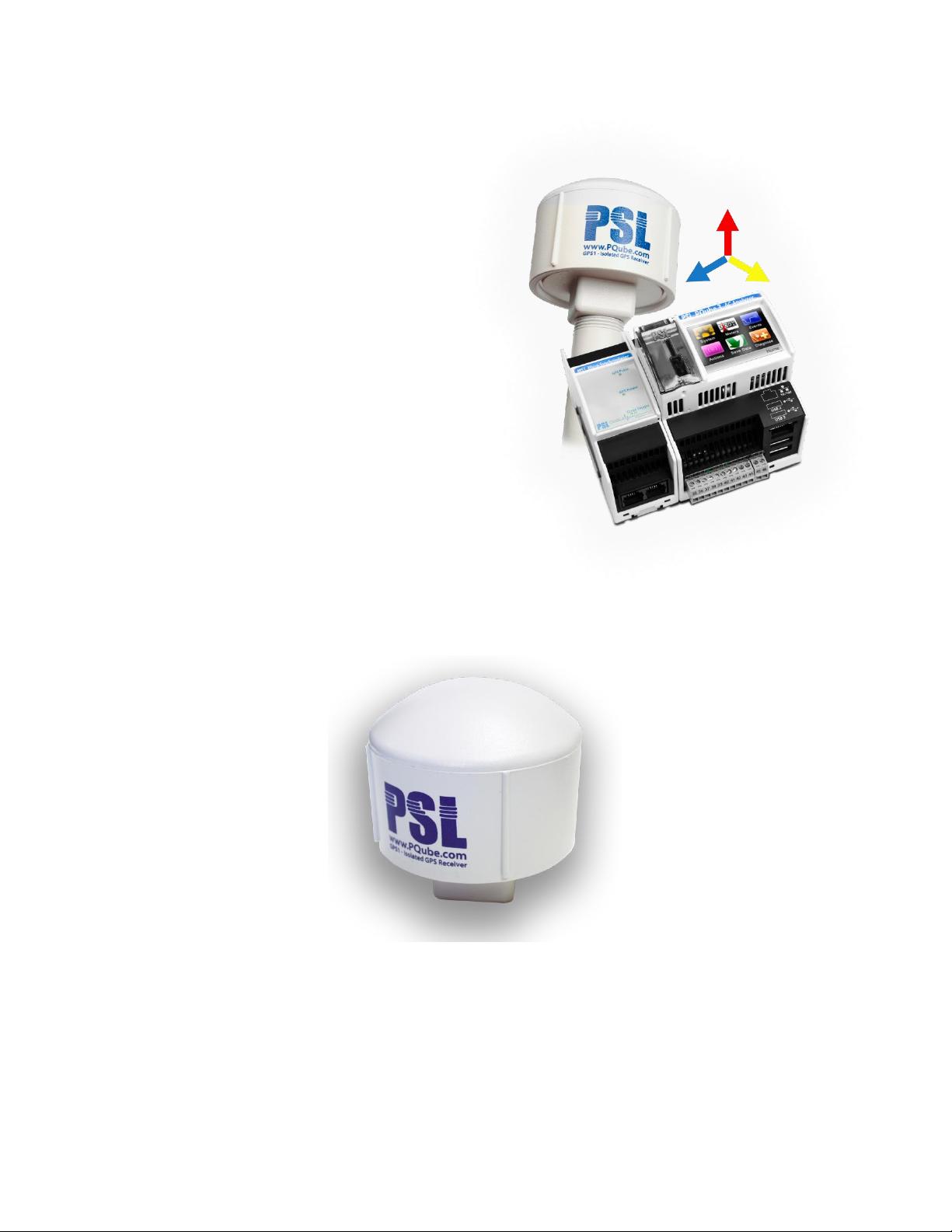
MS1 synchronization module and
GPS1 Receiver (required)
If you need ultra-precise GPS timestamps, or
if you want to perform micro-synchrophasor
measurements, connect the MS1 Sync
module with the GPS1 receiver to the left side
of your microPMU.
Figure 3 microPMU and GPS Antenna
The MS1 module interfaces with the GPS1 receiver to provide your microPMU with ultra-precise GPS
timing.
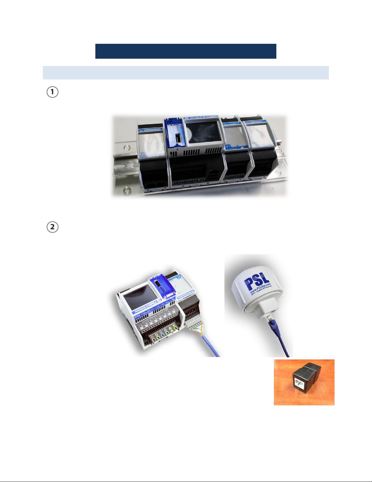
The GPS1 receiver locks onto GPS satellites in the sky to provide your microPMU with ultra-precise
GPS timing. It is designed to be weather-resistant and you can install it outside using optional
mounting hardware. It has 600V isolation at both ends of the cable for safety.
Figure 4 GPS Antenna
microPMU Installation and User’s Manual 2.0
Page 10 of 53
UPS1 Module - Backup your microPMU during a power outage (optional)
Figure 5 microPMU and UPS module
Connect the UPS1 Battery Backup module to your microPMU to provide up to 30 minutes of back
up power during a power outage. It can be used with or without a PM1 module.
Options for up to 3 hours with a UPS2 module are available.
microPMU Installation and User’s Manual 2.0
Page 11 of 53
Installation
Quickstart Guide
Assemble your modules together
Snap in the MS1 module to the left of your microPMU. If using a PM1 module and/or UPS1 module,
snap them into the right side of your microPMU.
Figure 6 Typical micro PMU with GPS, Power Supply and UPS
GPS setup
Your GPS cable has an 8-pin terminal block on one end and an RJ-45 jack on the other end. The 8-pin
terminal block plugs into the back of your MS1 module, the other end plugs into the GPS1 receiver.
Figure 7 GPS Connections
剩余52页未读,继续阅读
taitan27149
- 粉丝: 0
- 资源: 10
上传资源 快速赚钱
- 我的内容管理 展开
- 我的资源 快来上传第一个资源
- 我的收益 登录查看自己的收益
- 我的积分 登录查看自己的积分
- 我的C币 登录后查看C币余额
- 我的收藏
- 我的下载
- 下载帮助
最新资源
- 最优条件下三次B样条小波边缘检测算子研究
- 深入解析:wav文件格式结构
- JIRA系统配置指南:代理与SSL设置
- 入门必备:电阻电容识别全解析
- U盘制作启动盘:详细教程解决无光驱装系统难题
- Eclipse快捷键大全:提升开发效率的必备秘籍
- C++ Primer Plus中文版:深入学习C++编程必备
- Eclipse常用快捷键汇总与操作指南
- JavaScript作用域解析与面向对象基础
- 软通动力Java笔试题解析
- 自定义标签配置与使用指南
- Android Intent深度解析:组件通信与广播机制
- 增强MyEclipse代码提示功能设置教程
- x86下VMware环境中Openwrt编译与LuCI集成指南
- S3C2440A嵌入式终端电源管理系统设计探讨
- Intel DTCP-IP技术在数字家庭中的内容保护
资源上传下载、课程学习等过程中有任何疑问或建议,欢迎提出宝贵意见哦~我们会及时处理!
点击此处反馈
安全验证
文档复制为VIP权益,开通VIP直接复制
信息提交成功