单精度浮点数标准:IEEE 754在计算机中的应用与优势

版权申诉
0 下载量 93 浏览量 更新于2024-08-25 收藏 80KB DOCX 举报
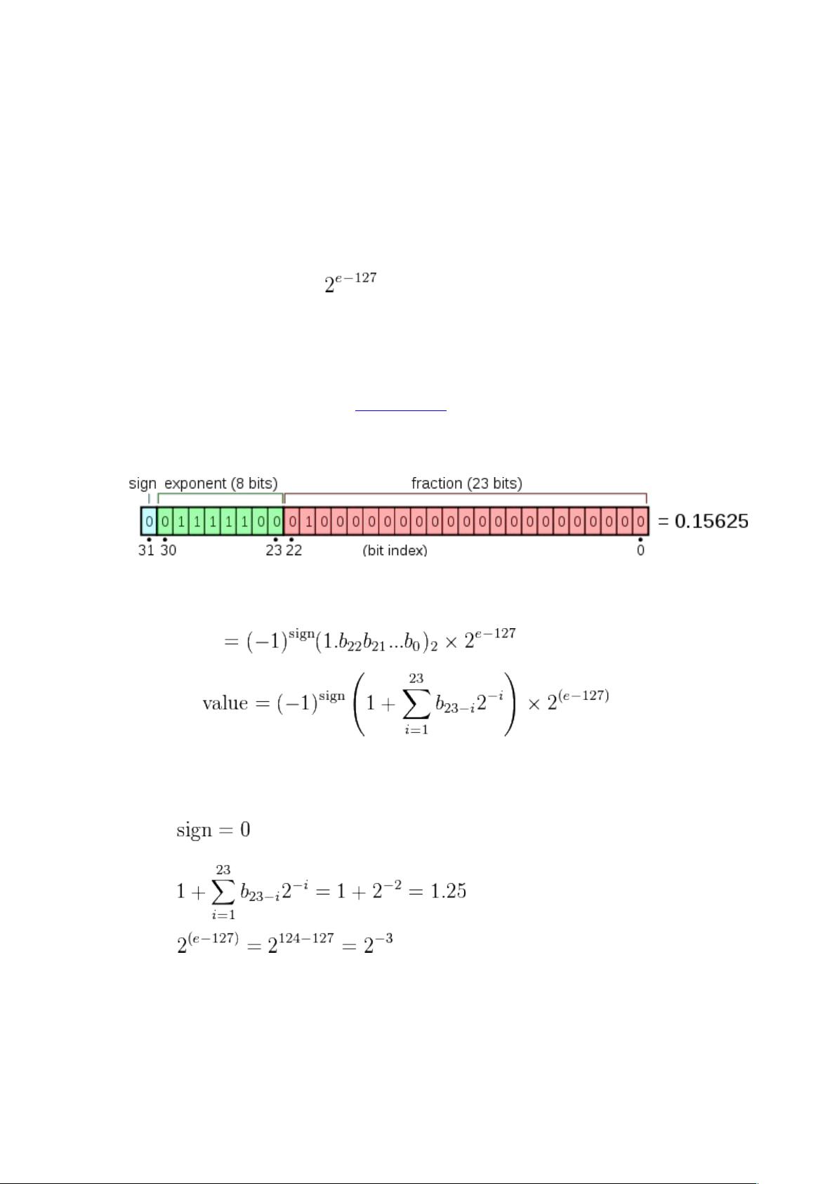
IEEE 754标准是计算机科学中的一项关键标准,它定义了单精度浮点数(也称为单精度或32位浮点数)在计算机中的表示方法和操作。这项标准最初在1985年的IEEE 754-1985中提出,之后在2008年的IEEE 754-2008版本中得到了更新。单精度浮点数占用4个字节(32位),旨在提供广泛的动态范围,通过使用二进制表示法来精确表示数值。 单精度浮点数的主要优势在于其比固定点数(具有相同比特宽度)能覆盖更大的数值范围,尽管牺牲了一些精度。这种格式在编程语言中被广泛采用,例如在Fortran中,单精度被称为REAL;在C、C++、C#、Java中是float;在Haskell中是single;在Delphi、Visual Basic以及MATLAB中,它们也以单精度命名。然而,值得注意的是,在Python、Ruby、PHP和早期版本的Octave(3.2之前)中,float可能指的是双精度类型,而不是单精度。 在早期的计算机时代,由于缺乏统一的标准,不同的计算机制造商可能会采用不同的浮点数格式,这导致了编程上的不一致性和兼容性问题。IEEE 754标准的引入解决了这个问题,为不同系统间的数据交换和计算提供了标准化的方法。该标准定义了数据的存储格式、运算规则以及异常处理机制,如溢出、下溢、无穷大和NaN(非数字)的处理。 此外,单精度浮点数的精度大约为7位小数,这意味着它能够精确表示大约16位有效数字。对于大多数日常计算任务,这已经足够,但对于需要高精度的科学计算或者财务应用,双精度浮点数(如64位)更为常用。尽管如此,单精度因其效率和内存占用的优势,在许多场合下仍然是首选的数值类型。 IEEE 754标准的单精度浮点数格式对于现代计算机科学和技术的发展起到了关键作用,它是计算机科学基础架构中不可或缺的一部分,确保了不同系统间的互操作性和性能优化。

在保持原来的代码逻辑的条件下,根据STM32F407的特性,把下面STM32F1的代码移植到STM32F407。void ExtiGpioInit(void) { GPIO_InitTypeDef GPIO_InitStruct; RCC_APB2PeriphClockCmd(RCC_APB2Periph_GPIOC|RCC_APB2Periph_AFIO, ENABLE); GPIO_InitStruct.GPIO_Mode = GPIO_Mode_IN_FLOATING; GPIO_InitStruct.GPIO_Pin = GPIO_Pin_4|GPIO_Pin_5 ; GPIO_InitStruct.GPIO_Speed = GPIO_Speed_50MHz; GPIO_Init(GPIOC, &GPIO_InitStruct); } void ExtiNvicInit(void) { NVIC_InitTypeDef NVIC_InitStructure; NVIC_InitStructure.NVIC_IRQChannel = EXTI4_IRQn; NVIC_InitStructure.NVIC_IRQChannelPreemptionPriority = 0; NVIC_InitStructure.NVIC_IRQChannelSubPriority = 1; NVIC_InitStructure.NVIC_IRQChannelCmd = ENABLE; NVIC_Init(&NVIC_InitStructure); NVIC_InitStructure.NVIC_IRQChannel = EXTI9_5_IRQn ; NVIC_InitStructure.NVIC_IRQChannelPreemptionPriority = 0; NVIC_InitStructure.NVIC_IRQChannelSubPriority = 2; NVIC_InitStructure.NVIC_IRQChannelCmd = ENABLE; NVIC_Init(&NVIC_InitStructure); } void ExtiModeInit(void) { EXTI_InitTypeDef EXTI_InitStructure; GPIO_EXTILineConfig(GPIO_PortSourceGPIOC, GPIO_PinSource4); EXTI_InitStructure.EXTI_Mode = EXTI_Mode_Interrupt; EXTI_InitStructure.EXTI_Trigger = EXTI_Trigger_Falling; EXTI_InitStructure.EXTI_Line = EXTI_Line4; EXTI_InitStructure.EXTI_LineCmd = ENABLE; EXTI_Init(&EXTI_InitStructure); GPIO_EXTILineConfig(GPIO_PortSourceGPIOC, GPIO_PinSource5); EXTI_InitStructure.EXTI_Mode = EXTI_Mode_Interrupt; EXTI_InitStructure.EXTI_Trigger = EXTI_Trigger_Falling; EXTI_InitStructure.EXTI_Line = EXTI_Line5; EXTI_InitStructure.EXTI_LineCmd = ENABLE; EXTI_Init(&EXTI_InitStructure); }

2023-07-09 上传

#include "stm32f10x.h"#include "stdio.h"#define RX_BUFFER_SIZE 9uint8_t rx_buffer[RX_BUFFER_SIZE];uint8_t rx_index = 0;void USART1_Init(void){ GPIO_InitTypeDef GPIO_InitStructure; USART_InitTypeDef USART_InitStructure; // 打开USART1和GPIOA时钟 RCC_APB2PeriphClockCmd(RCC_APB2Periph_USART1 | RCC_APB2Periph_GPIOA, ENABLE); // 配置USART1的GPIO引脚 GPIO_InitStructure.GPIO_Pin = GPIO_Pin_9; GPIO_InitStructure.GPIO_Mode = GPIO_Mode_AF_PP; GPIO_InitStructure.GPIO_Speed = GPIO_Speed_50MHz; GPIO_Init(GPIOA, &GPIO_InitStructure); GPIO_InitStructure.GPIO_Pin = GPIO_Pin_10; GPIO_InitStructure.GPIO_Mode = GPIO_Mode_IN_FLOATING; GPIO_Init(GPIOA, &GPIO_InitStructure); // 配置USART1的通信参数 USART_InitStructure.USART_BaudRate = 9600; USART_InitStructure.USART_WordLength = USART_WordLength_8b; USART_InitStructure.USART_StopBits = USART_StopBits_1; USART_InitStructure.USART_Parity = USART_Parity_No; USART_InitStructure.USART_HardwareFlowControl = USART_HardwareFlowControl_None; USART_InitStructure.USART_Mode = USART_Mode_Rx | USART_Mode_Tx; USART_Init(USART1, &USART_InitStructure); // 打开USART1 USART_Cmd(USART1, ENABLE);}void USART1_IRQHandler(void){ if (USART_GetITStatus(USART1, USART_IT_RXNE) == SET) { uint8_t data = USART_ReceiveData(USART1); if (rx_index < RX_BUFFER_SIZE) { rx_buffer[rx_index++] = data; } if (rx_index == RX_BUFFER_SIZE) { USART_ITConfig(USART1, USART_IT_RXNE, DISABLE); } }}int main(void){ USART1_Init(); while (1) { // 发送查询指令 USART_SendData(USART1, 0xFF); USART_SendData(USART1, 0x01); USART_SendData(USART1, 0x86); USART_SendData(USART1, 0x00); USART_SendData(USART1, 0x00); USART_SendData(USART1, 0x00); USART_SendData(USART1, 0x00); USART_SendData(USART1, 0x00); USART_SendData(USART1, 0x79); // 等待数据接收完成 rx_index = 0; USART_ITConfig(USART1, USART_IT_RXNE, ENABLE); while (rx_index < RX_BUFFER_SIZE); // 计算甲醛浓度 uint16_t ch2o_raw = (rx_buffer[2] << 8) | rx_buffer[3]; float ch2o_conc = ch2o_raw / 1000.0; // 显示甲醛浓度 printf("CH2O Concentration: %.3f mg/m3\r\n", ch2o_conc); // 等待一段时间后再进行下一次检测 delay_ms(1000); }}void delay_ms(uint32_t ms){ uint32_t i, j; for (i = 0; i < ms; i++) for (j = 0; j < 2000; j++);}代码中串口是不是错了,应该是usart3吧

2023-05-27 上传

为下面每一行代码添加注释:#include "stm32f10x.h" void RCC_Configuration(void) { /* Enable GPIOA, GPIOC and AFIO clocks / RCC_APB2PeriphClockCmd(RCC_APB2Periph_GPIOA | RCC_APB2Periph_GPIOC | RCC_APB2Periph_AFIO, ENABLE); / Enable SYSCFG clock / RCC_APB2PeriphClockCmd(RCC_APB2Periph_SYSCFG, ENABLE); } void GPIO_Configuration(void) { GPIO_InitTypeDef GPIO_InitStructure; / Configure PA0 pin as input floating / GPIO_InitStructure.GPIO_Pin = GPIO_Pin_0; GPIO_InitStructure.GPIO_Mode = GPIO_Mode_IN_FLOATING; GPIO_Init(GPIOA, &GPIO_InitStructure); / Configure PC13 pin as output push-pull / GPIO_InitStructure.GPIO_Pin = GPIO_Pin_13; GPIO_InitStructure.GPIO_Speed = GPIO_Speed_50MHz; GPIO_InitStructure.GPIO_Mode = GPIO_Mode_Out_PP; GPIO_Init(GPIOC, &GPIO_InitStructure); } void NVIC_Configuration(void) { NVIC_InitTypeDef NVIC_InitStructure / Configure the NVIC Preemption Priority Bits / NVIC_PriorityGroupConfig(NVIC_PriorityGroup_0); / Enable the EXTI0 Interrupt / NVIC_InitStructure.NVIC_IRQChannel = EXTI0_IRQn; NVIC_InitStructure.NVIC_IRQChannelPreemptionPriority = 0; NVIC_InitStructure.NVIC_IRQChannelSubPriority = 0; NVIC_InitStructure.NVIC_IRQChannelCmd = ENABLE; NVIC_Init(&NVIC_InitStructure); } void EXTI_Configuration(void) { EXTI_InitTypeDef EXTI_InitStructure; / Configure EXTI Line0 to generate an interrupt on falling edge / EXTI_InitStructure.EXTI_Line = EXTI_Line0; EXTI_InitStructure.EXTI_Mode = EXTI_Mode_Interrupt; EXTI_InitStructure.EXTI_Trigger = EXTI_Trigger_Falling; EXTI_InitStructure.EXTI_LineCmd = ENABLE; EXTI_Init(&EXTI_InitStructure); / Connect EXTI Line0 to PA0 pin / GPIO_EXTILineConfig(GPIO_PortSourceGPIOA, GPIO_PinSource0); } void SysTick_Configuration(void) { / Configure SysTick to generate an interrupt every 1ms / if (SysTick_Config(SystemCoreClock / 1000)) { / Capture error / while (1); } } void Delay(__IO uint32_t nTime) { / Wait for nTime millisecond / TimingDelay = nTime; while (TimingDelay != 0); } void TimingDelay_Decrement(void) { if (TimingDelay != 0x00) { TimingDelay--; } } int main(void) { RCC_Configuration(); GPIO_Configuration(); NVIC_Configuration(); EXTI_Configuration(); SysTick_Configuration(); / Infinite loop / while (1) { / Toggle PC13 LED every 500ms / GPIOC->ODR ^= GPIO_Pin_13; Delay(500); } } void EXTI0_IRQHandler(void) { / Check if PA0 button is pressed / if (GPIO_ReadInputDataBit(GPIOA, GPIO_Pin_0) == RESET) { / Reset MCU / NVIC_SystemReset(); } / Clear EXTI Line0 pending bit */ EXTI_ClearITPendingBit(EXTI_Line0); }

2023-06-03 上传