
SGLS171A − JUNE 2003 − REVISED DECEMBER 2003
7
POST OFFICE BOX 655303 • DALLAS, TEXAS 75265
input data bits
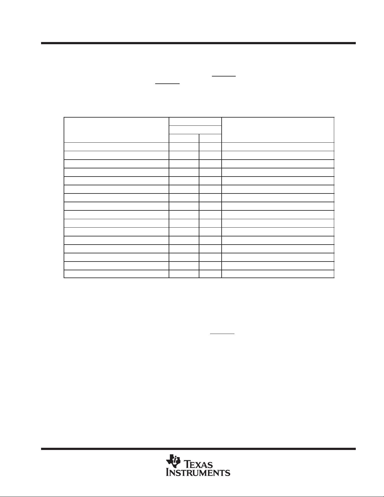
DATA IN is internally connected to a 4-bit serial input data register. The input data selects a different mode or
selects different analog input channels. The host provides the data word with the MSB first. Each data bit clocks
in on the edge (rising or falling depending on the status of INV CLK
and FS) of the I/O CLK sequence. The input
clock can be inverted by grounding INV CLK
(see Table 3 for the list of software programmed operations set
by the input data).
Table 3. TLV1548 Software-Programmed Operation Modes
INPUT DATA BYTE
FUNCTION SELECT
A3 − A0
COMMENT
FUNCTION SELECT
BINARY HEX
COMMENT
Analog channel A0 for TLV1548 selected 0000b 0h
Analog channel A1 for TLV1548 selected 0001b 1h
Analog channel A2 for TLV1548 selected 0010b 2h
Analog channel A3 for TLV1548 selected 0011b 3h
Analog channel A4 for TLV1548 selected 0100b 4h
Analog channel A5 for TLV1548 selected 0101b 5h
Analog channel A6 for TLV1548 selected 0110b 6h
Analog channel A7 for TLV1548 selected 0111b 7h
Software power down set 1000b 8h No conversion result (cleared by any access)
Fast conversion rate (10 µs) set 1001b 9h No conversion result (cleared by setting to fast)
Slow conversion rate (40 µs) set 1010b Ah No conversion result (cleared by setting to slow)
Self-test voltage (V
ref)
− V
ref−
)/2 selected 1011b Bh Output result = 200h
Self-test voltage V
ref*
selected 1100b Ch Output result = 000h
Self-test voltage V
ref)
selected 1101b Dh Output result = 3FFh
Reserved 1110b Eh No conversion result
Reserved 1111b Fh No conversion result
analog inputs and internal test voltages
The eight analog inputs and the three internal test inputs are selected by the 11-channel multiplexer according
to the input data bit as shown in Table 3. The input multiplexer is a break-before-make type to reduce
input-to-input noise injection resulting from channel switching.
The device can be operated in two distinct sampling modes: normal sampling mode (fixed sampling time) and
extended sampling mode (flexible sampling time). When CSTART
is held high, the device is operated in normal
sampling mode. When operated in normal sampling mode, sampling of the analog input starts on the rising edge
of the fourth I/O CLK pulse in the microprocessor interface mode (and on the fourth falling edge of I/O CLK in
the DSP interface mode). Sampling continues for 6 I/O CLK periods. The sample is held on the falling edge of
the tenth I/O CLK pulse in the microprocessor interface mode. The sample is held on the falling edge of the tenth
I/O CLK pulse in the DSP interface mode.The three test inputs are applied to the multiplexer, then sampled and
converted in the same manner as the external analog inputs.

剩余35页未读,继续阅读

不觉明了
- 粉丝: 3281
- 资源: 5614
 我的内容管理
收起
我的内容管理
收起
- 我的资源
快来上传第一个资源
 我的收益 登录查看自己的收益
 我的积分
登录查看自己的积分
我的积分
登录查看自己的积分
 我的C币
登录后查看C币余额
我的C币
登录后查看C币余额
 我的收藏
我的收藏  我的下载
我的下载  下载帮助
下载帮助

会员权益专享


最新资源
- Simulink在电机控制仿真中的应用
- 电子警察:功能、结构与抓拍原理详解
- TESSY 4.1 英文用户手册:Razorcat Development GmbH
- 5V12V直流稳压电源设计及其实现
- 江西建工四建来宾市消防支队高支模施工方案
- 三维建模教程:创建足球模型
- 宏福苑南二区公寓楼施工组织设计
- 福建外运集团信息化建设技术方案:网络与业务平台设计
- 打造理想工作环境:详尽的6S推行指南
- 阿里巴巴数据中台建设与实践
- 欧姆龙CP1H PLC操作手册:SYSMACCP系列详解
- 中国移动统一DPI设备技术规范:LTE数据合成服务器关键功能详解
- 高校竞赛信息管理系统:软件设计与体系详解
- 面向对象设计:准则、启发规则与系统分解
- 程序设计基础与算法解析
- 算法与程序设计基础概览
资源上传下载、课程学习等过程中有任何疑问或建议,欢迎提出宝贵意见哦~我们会及时处理!
点击此处反馈


