
Designing the VCNL4040 Into an Application
Application Note
www.vishay.com
Vishay Semiconductors
APPLICATION NOTE
Revision: 12-Nov-2019
4
Document Number: 84307
For technical questions, contact: sensorstechsupport@vishay.com
THIS DOCUMENT IS SUBJECT TO CHANGE WITHOUT NOTICE. THE PRODUCTS DESCRIBED HEREIN AND THIS DOCUMENT
ARE SUBJECT TO SPECIFIC DISCLAIMERS, SET FORTH AT www.vishay.com/doc?91000
Fig. 10 - Light Holes Diameters
The diameter needs to be increased with distances between
the sensor and cover glass according to the following
calculation.
The width calculation for distances from 0 mm to 4 mm
results with this in:
a = 0.0 mm → x = 0.0 → d = 4.0 mm + 0.0 = 4.0 mm
a = 0.5 mm → x = 0.42 → d = 4.0 mm + 0.84 = 4.84 mm
a = 1.0 mm → x = 0.84 → d = 4.0 mm + 1.68 = 5.68 mm
a = 1.5 mm → x = 1.28 → d = 4.0 mm + 2.56 = 6.56 mm
a = 2.0 mm → x = 1.68 → d = 4.0 mm + 3.36 = 7.36 mm
a = 2.5 mm → x = 2.10 → d = 4.0 mm + 4.20 = 8.20 mm
a = 3.0 mm → x = 2.52 → d = 4.0 mm + 5.04 = 9.04 mm
a = 3.5 mm → x = 2.94 → d = 4.0 mm + 5.88 = 9.58 mm
a = 4.0 mm → x = 3.36 → d = 4.0 mm + 6.72 = 10.72 mm
For the two smaller holes, the diameter for the IRED can be
as small as 1.2 mm.
Fig. 11 - Window Diameters for Two Holes
Only the diameter for the photodiode needs to be increased,
as shown in the example below, with distances between the
sensor and cover glass.
The width calculation for distances from 0 mm to 1.5 mm
results in:
a = 0.0 mm → x = 0.0 → d = 1.2 mm + 0.0 = 1.2 mm
a = 0.5 mm → x = 0.42 → d = 1.2 mm + 0.84 = 2.04 mm
a = 1.0 mm → x = 0.84 → d = 1.2 mm + 1.68 = 2.88 mm
a = 1.5 mm → x = 1.28 → d = 1.2 mm + 2.56 = 3.76 mm
The results above represent the ideal diameters of the
window. The mechanical design of the device may not allow
for these diameters.
PROXIMITY SENSOR
The main DC light sources found in the environment are
sunlight and tungsten (incandescent) bulbs. These kinds of
disturbance sources will cause a DC current in the detector
inside the sensor, which in turn will produce noise in the
receiver circuit. The negative influence of this DC light can
be reduced by optical filtering, but is reduced much more
efficiently by a so-called DC kill function. The proximity
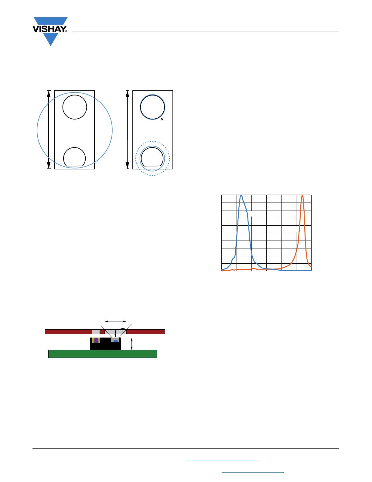
photodiode shows its best sensitivity at about 940 nm, as
shown in fig. 12.
Fig. 12 - Spectral Sensitivity of ALS and Proximity Photodiode
The proximity sensor uses a short pulse signal of about
100 μs (PS_IT = 1T) up to 800 μs (PS_IT = 8T). The on / off
duty ratio setting now defines which repetition rate to be
used, which can be programmed from 1/40 up to 1/320.
In addition to DC light source noise, there is some reflection
of the infrared emitted light off the surfaces of the
components surrounding the VCNL4040. The distance to
the cover, proximity of surrounding components, tolerances
of the sensor, defined infrared emitter current, ambient
temperature, and type of window material used all
contribute to this reflection. The result of the reflection and
DC noise is the production of an output current on the
proximity and light sensing photodiode. This current is
converted into a count called the offset count.
In addition to the offset count, there could also be a small
noise floor during the proximity measurement, which comes
from the DC light suppression circuitry. This noise is
typically just one or two counts. Only with light sources with
strong infrared content could it be in the range from
± 5 counts to ± 10 counts.
4 ± 0.1
Ø 1.2
4 ± 0.1
d1
x
α
a
1.1
dimensions in mm
D
10
100
1000
10000
0
10
20
30
40
50
60
70
80
90
100
400 500 600 700 800 900 1000
Axis Title
1st line
2nd line
1st line
2nd line
Relative Response (%)
Wavelength (nm)
PS
ALS
剩余15页未读,继续阅读

wzy8430121
- 粉丝: 2
- 资源: 23
 我的内容管理
展开
我的内容管理
展开


最新资源
- 最优条件下三次B样条小波边缘检测算子研究
- 深入解析:wav文件格式结构
- JIRA系统配置指南:代理与SSL设置
- 入门必备:电阻电容识别全解析
- U盘制作启动盘:详细教程解决无光驱装系统难题
- Eclipse快捷键大全:提升开发效率的必备秘籍
- C++ Primer Plus中文版:深入学习C++编程必备
- Eclipse常用快捷键汇总与操作指南
- JavaScript作用域解析与面向对象基础
- 软通动力Java笔试题解析
- 自定义标签配置与使用指南
- Android Intent深度解析:组件通信与广播机制
- 增强MyEclipse代码提示功能设置教程
- x86下VMware环境中Openwrt编译与LuCI集成指南
- S3C2440A嵌入式终端电源管理系统设计探讨
- Intel DTCP-IP技术在数字家庭中的内容保护
资源上传下载、课程学习等过程中有任何疑问或建议,欢迎提出宝贵意见哦~我们会及时处理!
点击此处反馈


