"野火_EP4CE10_Pro_原理图历史版本详解,主电源至各模块接口一览"。
需积分: 0 166 浏览量
更新于2024-03-20
收藏 351KB PDF 举报
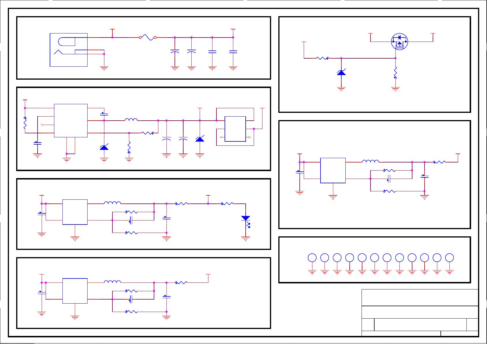
The document titled "ebf EP4CE10 Pro_20200309_原理图1" is a comprehensive schematic diagram detailing the various components and connections of the Wildfire EP4CE10 Pro development board. The document is organized into sections including the main power supply, camera/SPI flash/EEPROM, Ethernet, sensors/buttons/LEDs, audio, LED displays/RTC, and IO interfaces.
The history of the document includes previous versions and revisions made to the schematic diagram. The main power supply section outlines the circuitry responsible for powering the board and its components. The MCU_GPIO1 section covers microcontroller GPIO pin connections, SDRAM, and communication interfaces such as UART/CAN/RS232/RS485.
The camera/SPI flash/EEPROM section details the connections for these components, while the Ethernet section outlines the networking capabilities of the board. Sensors, buttons, LEDs, and audio components are also included in the document, along with VGA/LCD/ADC/DAC/JTAG connections, LED displays, and RTC.
The HDMI and IO interfaces are also highlighted in the schematic diagram, showcasing the various input/output options available on the development board. The document includes multiple pages with detailed diagrams and annotations to help users understand the layout and functionality of each component.
Overall, the Wildfire EP4CE10 Pro schematic diagram provides a comprehensive overview of the development board's design and capabilities, serving as a valuable reference for engineers and developers working on projects involving FPGA technology. The document is created by Dongguan Wildfire Electronic Technology Co., Ltd., and is available for download on their official website.
5
5
4
4
3
3
2
2
1
1
D
C
B
A A
5A
DC/DC 12V To 5V
外部电源供电时断开
USB
供电,防止灌电流,保护电脑
USB
口
定位孔
DC IN : 6V~12V
0.6V
最大电流
1000mA
3.3V
DC/DC 5V To 3.3V
0.6V
最大电流
1000mA
2.5V
DC/DC 5V To 2.5V
0.6V
最大电流
1000mA
1.2V
DC/DC 5V To 1.2V
GND GND GND
12V
12V
GND
GND GND
5V_USB
GND GND
12V_IN
12V_IN
GND GND GND GND GND GND GND
5V_IN
GND
GNDGND
5V_IN
GND GND
GND GND
GND
GND GND
5V
GND
5V
GND
GND
GND GND
3V3
5V
GND
GND
GND
2V5
5V
GND
GND
GND
1V2
Title
Size
Document Number
Rev
Date: Sheet of
电源供电
V1.0
野火
_EP4CE10_Pro_
原理图
东莞野火电子技术有限公司
https://fire-stm32.taobao.com
A4
3 15Friday, January 03, 2020
Title
Size
Document Number
Rev
Date: Sheet of
电源供电
V1.0
野火
_EP4CE10_Pro_
原理图
东莞野火电子技术有限公司
https://fire-stm32.taobao.com
A4
3 15Friday, January 03, 2020
Title
Size
Document Number
Rev
Date: Sheet of
电源供电
V1.0
野火
_EP4CE10_Pro_
原理图
东莞野火电子技术有限公司
https://fire-stm32.taobao.com
A4
3 15Friday, January 03, 2020
Q1
SSM3J328R
1
32
U3 RT8096CHGJ5
VIN
4
EN
1
GND
2
FB
5
LX
3
R14 124K
R0603
1%
U5 RT8096CHGJ5
VIN
4
EN
1
GND
2
FB
5
LX
3
R7 30K
R0603
1%
C12 68pF
C0603 6.3V
C4
10uF
D3
MBRS540T3
1 2
L4
2.2uH
1 2
+
C2
NC
H1
3.0mm
C10 68pF
C0603 6.3V
R12 20K
R0603
1%
U1
MP2482DN
IN
8
VCC
3
PG
6
EN
7
BST
2
SW
1
FB
5
GND
4
E
9
R5
7.68K
C15 68pF
C0603 6.3V
D2
SMAJ5.0CA
1 2
H5
3.0mm
+
C6
100uF/16V
H9
3.0mm
H10
3.0mm
R8 30K
R0603
1%
C14
47uF
4V
C0603
C3
0.1uF
L1
FXC1040-100M
1 2
R15 39K
R0603
1%
SW6
POWER-SWICH
6
6
5
5
4
4
3
3
2
2
1
1
C13
10uF
10V
C0603
+
C1
100uF/16V
D1
ZMM5V6
1 2
C11
47uF
4V
C0603
C8
1uF
D4
RED
12
F1
0R
C17
47uF
4V
C0603
C9
10uF
10V
C0603
H3
3.0mm
R10 1K
C16
10uF
10V
C0603
R3
4.7K
R9 0R
R0603
R1
4.7K
H4
3.0mm
H6
3.0mm
R11 90K
R0603
1%
R6 0R
R0603
+
C7
NC
H7
3.0mm
R13 0R
R0603
H2
3.0mm
U4 RT8096CHGJ5
VIN
4
EN
1
GND
2
FB
5
LX
3
L3
2.2uH
1 2
H8
3.0mm
JACK1
POWER JACK_3
P
1
G2
2
G3
3
L2
2.2uH
1 2
R2
47K
H11
3.0mm
R4 40.2K
H12
3.0mm
C5
0.1uF
DCDC_3V3_1
DCDC_2V5_1
DCDC_1V2_1
剩余14页未读,继续阅读
2022-08-03 上传
2022-12-18 上传
2021-05-11 上传
2022-08-03 上传
2019-05-22 上传
点击了解资源详情
2024-10-27 上传

挽挽深铃
- 粉丝: 18
- 资源: 274
 我的内容管理
展开
我的内容管理
展开


最新资源
- C++ Qt影院票务系统源码发布,代码稳定,高分毕业设计首选
- 纯CSS3实现逼真火焰手提灯动画效果
- Java编程基础课后练习答案解析
- typescript-atomizer: Atom 插件实现 TypeScript 语言与工具支持
- 51单片机项目源码分享:课程设计与毕设实践
- Qt画图程序实战:多文档与单文档示例解析
- 全屏H5圆圈缩放矩阵动画背景特效实现
- C#实现的手机触摸板服务端应用
- 数据结构与算法学习资源压缩包介绍
- stream-notifier: 简化Node.js流错误与成功通知方案
- 网页表格选择导出Excel的jQuery实例教程
- Prj19购物车系统项目压缩包解析
- 数据结构与算法学习实践指南
- Qt5实现A*寻路算法:结合C++和GUI
- terser-brunch:现代JavaScript文件压缩工具
- 掌握Power BI导出明细数据的操作指南
