NXP PN7120: NFC Controller for Seamless Integration
"NXP PN7120 NFC 控制器技术文档"
NXP PN7120是一款先进的近场通信(NFC)控制器,专为简单集成到各种操作系统环境而设计,尤其适用于运行Linux和Android等操作系统的应用。该芯片提供了一个完整的即插即用的全NFC解决方案,显著降低了物料清单(BOM)的尺寸和成本。
**1. 功能特性**
PN7120的主要特点是其全面符合NFC论坛标准,这使得它能够与小型天线一起工作,确保了在13.56MHz频段进行无接触通信的兼容性和效率。其嵌入式NFC固件预集成了所有NFC协议,简化了系统集成过程,无需额外开发工作。
**2. I2C总线和NCI接口**
PN7120通过I2C总线物理层和NFC接口(NCI)直接连接到主主机或微控制器,这种设计简化了硬件连接并优化了系统架构。NCI是NFC控制器接口,它定义了NFC控制器与主机系统之间的通信协议,确保不同组件间的互操作性。
**3. 超低功耗设计**
在轮询循环模式下,PN7120具有极低的功率消耗,这使得它非常适合于电池供电的设备。其内置的高效电源管理单元(PMU)允许直接从电池供电,进一步优化了能效。
**4. 集成的电源管理**
PN7120集成了高效的PMU,能够根据设备的运行状态动态调整电源供给,确保在保持功能的同时最大程度地降低能耗。这对于电池寿命至关重要的移动设备来说,是一个重要的优势。
**5. 应用场景**
由于其出色的兼容性和易集成性,PN7120广泛应用于各种领域,包括但不限于移动设备(如智能手机和平板电脑)、智能标签、支付终端、安全身份验证和物联网设备。它能够支持多种NFC应用,如接触式和非接触式支付、数据交换、智能海报互动以及设备配对。
**6. 设计支持**
NXP为PN7120提供了全面的技术文档和支持,包括设计指南、应用笔记和参考文献,以帮助开发者和制造商顺利进行产品开发和集成。
NXP PN7120是一个高性能、低功耗且易于集成的NFC解决方案,它为各种智能设备提供了一条快速进入NFC世界的通道,有助于提升用户体验并加速新产品上市进程。
PN7120 All information provided in this document is subject to legal disclaimers. © NXP Semiconductors N.V. 2015. All rights reserved.
Product data sheet
COMPANY PUBLIC
Rev. 3.1 — 8 October 2015
312431 10 of 55
NXP Semiconductors
PN7120
Full NFC Forum-compliant controller with integrated firmware
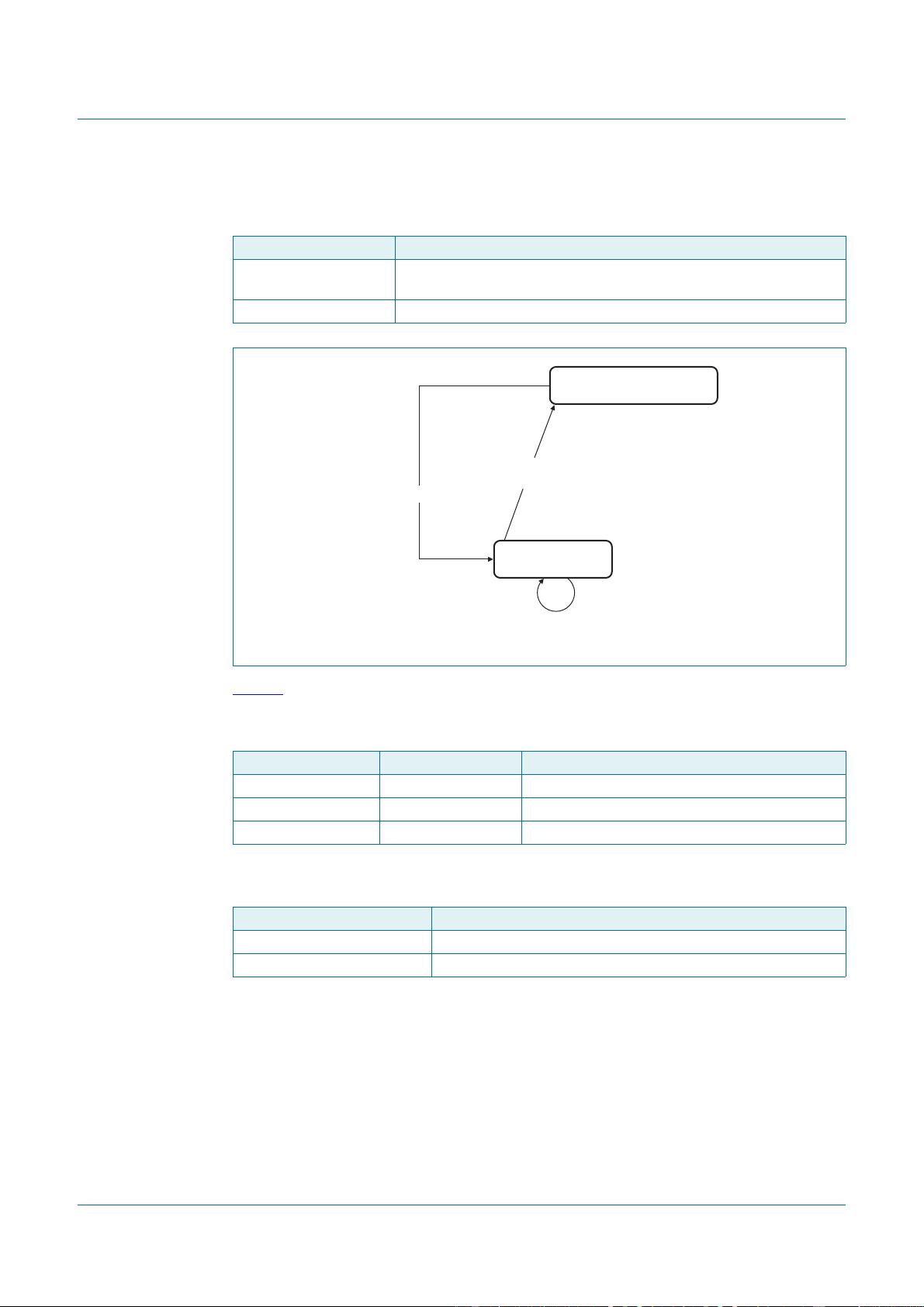
2 power modes are specified: Full power mode and Power Off mode.
Table 6 summarizes the system power mode of the PN7120 depending on the status of
the external supplies available in the system:
Depending on power modes, some application states are limited:
10.1.2 PN7120 power states
Next to system power modes defined by the status of the power supplies, the power
states include the logical status of the system thus extend the power modes.
4 power states are specified: Monitor, Hard Power Down (HPD), Standby, Active.
Table 5. System power modes description
System power mode Description
Full power mode the main supply (V
BAT
) as well as the host interface supply (V
DD(PAD)
) is
available, all use cases can be executed
Power Off mode the system is kept Hard Power Down (HPD)
Fig 6. System power mode diagram
Table 6. System power modes configuration
V
BAT
VEN Power mode
Off X Power Off mode
On Off Power Off mode
On On Full power mode
Table 7. System power modes description
System power mode Allowed communication modes
Power Off mode no communication mode available
Full power mode Reader/Writer, Card Emulation, P2P modes
aaa-015871
[VEN = Off]
[V
BAT
= On && V
DD(PAD)
= On
VEN = On]
[V
BAT
= Off || VEN = Off]
Full power mode
Power Off mode

剩余54页未读,继续阅读
1547 浏览量
102 浏览量
2024-10-26 上传
2024-10-26 上传
2024-10-26 上传
235 浏览量
135 浏览量
161 浏览量

u011680620
- 粉丝: 0
- 资源: 2
 我的内容管理
展开
我的内容管理
展开


最新资源
- pid控制器代码matlab-bobb:光束在光束平衡器上控制项目。有关更多详细信息,请参见dvernooy.github.io/projec
- java接口自动化案例
- css3 checkbox美化单选按钮和复选按钮美化样式
- 行业文档-设计装置-一种具有可移动风扇的笔记本散热器.zip
- cerbo:我的脑子里有什么
- awesome-farming:精心制作的一切的精选链接列表
- 德阁html.zip
- pid控制器代码matlab-Modeling-and-controlling-of-Electrical-DC-motor::在MATLAB
- 中国风创意书画展古风海报背景水墨书法
- CQL-Formatting-and-Usage-Wiki:一个协作工作区,用于开发用于工件开发的CQL格式约定和使用模式。 带有CQL示例的烹饪之家,请访问Wiki了解更多
- generation03
- jolloniego.github.io
- 像素:方格像素
- pid控制器代码matlab-Motor-PID-Controller-using-Arduino-Matlab:使用Arduino和Matl
- 牧场系统可视化系统 娱乐系统
- androidone:图形界面草图库,用于设计Android one应用程序
