RTL8181无线局域网控制器数据手册
需积分: 9 49 浏览量
更新于2024-07-26
收藏 513KB PDF 举报
"RTL8181是一款高度集成的系统级芯片,主要设计用于无线局域网接入点和网关控制器。此IC的数据手册详细介绍了其功能、引脚描述、地址映射、寄存器映射、系统配置、中断控制器、内存控制器、以太网控制器、UART控制器、定时器与看门狗、GPIO控制以及802.11b无线局域网控制器等关键部分。数据手册的修订历史记录了各个版本的更新内容,包括对系统配置的添加、寄存器用法的描述改进、引脚编号的增加、内存映射的更新以及对Maxim RF接口的引脚定义等。"
本文将深入探讨RTL8181集成电路的关键特性及其在无线局域网设备中的应用。
1. **概述**
RTL8181是一款专为无线局域网(WLAN)接入点和网关设计的单片系统(SoC),集成了多种功能,包括网络处理、内存管理、中断处理和无线通信。这款芯片旨在提供高效能、低功耗的解决方案,支持802.11b标准的无线连接。
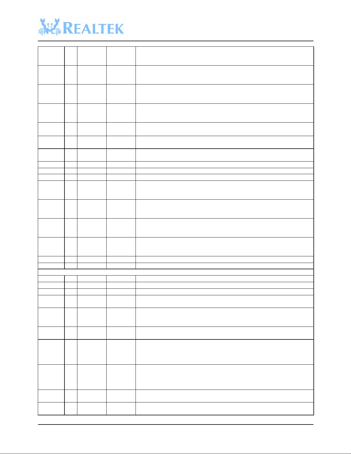
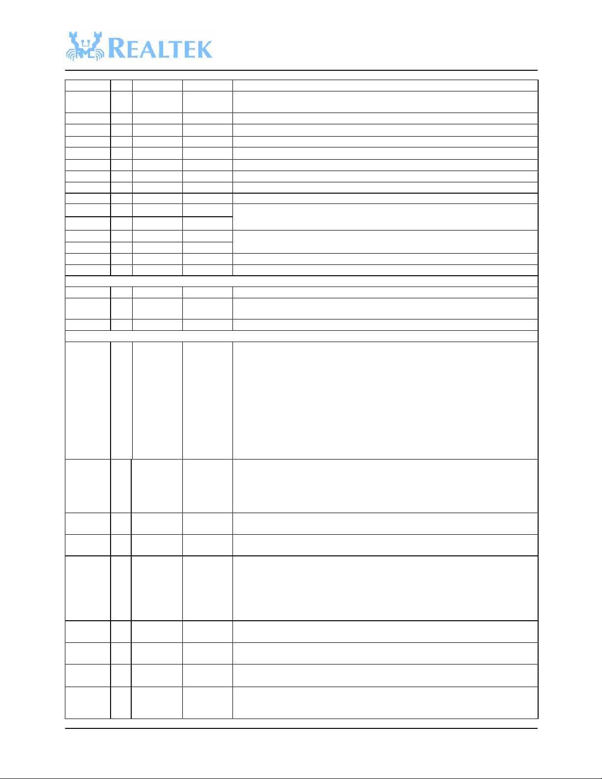
2. **引脚描述**
数据手册详细列出了RTL8181的所有引脚,包括它们的功能和电气特性,这对于电路板设计者来说是至关重要的信息,以确保正确连接和操作。
3. **地址映射**
地址映射部分详细定义了内部存储空间的分配,包括寄存器地址和内存区域,这对于编写驱动程序和控制软件至关重要。
4. **寄存器映射**
这一部分描述了每个寄存器的用途、地址和操作,这些寄存器用于控制和配置芯片的不同功能模块。
5. **系统配置**
系统配置章节提供了如何设置和调整RTL8181以适应不同应用场景的指导,包括对系统时钟、电源管理和初始化步骤的说明。
6. **中断控制器**
中断控制器部分阐述了如何管理和响应来自各个子系统的中断请求,确保高效的数据处理和事件响应。
7. **内存控制器**
内存控制器部分涵盖了如何访问和管理芯片内部及外部的内存资源,包括DRAM和SRAM的配置。
8. **以太网控制器**
以太网控制器章节详细介绍了如何使用RTL8181进行有线以太网连接,包括MAC层操作、帧传输和接收功能。
9. **UART控制器**
通用异步收发传输器(UART)控制器部分说明了如何通过串行接口与其他设备通信。
10. **定时器与看门狗**
定时器和看门狗功能对于系统稳定性和故障恢复至关重要,这部分描述了它们的工作原理和配置方法。
11. **GPIO控制**
GPIO(通用输入/输出)控制部分介绍了如何利用这些引脚实现灵活的硬件交互。
12. **802.11b WLAN控制器**
最后,802.11b WLAN控制器部分详细解释了如何利用RTL8181进行无线连接,包括射频接口、信道选择、加密和认证机制。
13. **封装信息**
封装信息提供了芯片的实际物理尺寸、引脚布局以及与其他组件的兼容性,有助于实际硬件设计。
RTL8181数据手册提供了全面的技术细节,为设计人员和开发工程师提供了构建基于该芯片的无线局域网设备所需的一切信息。通过理解和应用这些知识,可以创建出高效、可靠的网络设备。
RTL8181
CONFIDENTIAL v1.0
9
TRSWN O 79 L20 Transmit and Receive Switch Control: This is a complement for TRSW+.
1:RX
0:TX
VCOPDN/
PHITXI/
O/I 81 K20 Output Pin as Transmit (TX) In-phase Digital Data of the Philips Chipset. This
function is valid on Tx digital mode (AnalogPhy = Digital on EEPROM writer
program).
PAPE O 82 K19 Transmit PA Power Enable: Assert high when starting transmission.
PE1/PHIT
XQ
O 84 K18 Transmit (TX) Quadrature Digital Data of Philips Chipset. This function is valid
on Tx digital mode (AnalogPhy = Digital on EEPROM writer program).
PE2 O 85 J20 Output Pin as TX/RX Control:
1:RX
0:TX
RXIP AI* 110 B19 Receive (Rx) In-phase Analog Data: Positive path of differential pair.
RXIN AI 109 B20 Receive (Rx) In-phase Analog Data: Negative path of differential pair.
RXQP AI 106 C18 Receive (Rx) Quadrature-phase Analog Data: Positive path of the differential
pair.
RXQN AI 105 C19 Receive (Rx) Quadrature-phase Analog Data: Negative path of the differential
pair.
RSSI AI 103 D17 Received Signal Strength Indication: To internal ADC.
TXDET AI 102 D18 Transmit Power Detect: To internal ADC which detects transmit power.
VREFI AI 101 C20 Reference Voltage for ADC & DAC
TXIP AO 97 E19 Transmit (Tx) In-phase Analog Data: Positive path of differential pair. This
function is valid on Tx digital mode (AnalogPhy = Digital on EEPROM writer
program).
TXIN AO 96 F18 Transmit (Tx) In-phase Analog Data: Negative path of differential pair. This
function is valid on Tx digital mode (AnalogPhy = Digital on EEPROM writer
program).
TXQP AO 94 E20 Transmit (Tx) Quadrature-phase Analog Data: Positive path of the differential
pair. This function is valid on Tx digital mode (AnalogPhy = Digital on
EEPROM writer program).
TXQN AO 93 F20 Transmit (Tx) Quadrature-phase Analog Data: Negative path of the differential
pair. This function is valid on Tx digital mode (AnalogPhy = Digital on
EEPROM writer program).
TXAGC X 91 F19 Not used in Philips RF chipset
RXAGC X 90 G18 Not used in Philips RF chipset
RF Interface for Maxim
RIFSCK O 66 R20 3-wire Bus Clock: The serial clock output
RIFSD O 67 P19 3-wire Bus Data: Serial data output
RFLE O 68 P18 3-wire Bus Enable: Enable serial port output
IFLE/AGC
SET
X* 70 N18 Not used in the Maxim RF chipset.
CALEN/
AGCRESE
T
X 71 P20 Not used in the Maxim RF chipset.
LNA_HL O 73 M19 LNA Gain Select Logic Output: Logic high for LNA high-gain mode, logic low
for LNA low-gain mode.
ANTSELP
O 75 M20 Antenna Select +: The antenna selects signal changes state as the receiver
switches from antenna to antenna during the acquisition process in the antenna
diversity mode. This is a complement for ANTSEL- for differential drive of
antenna switches.
ANTSELN
X 76 L18 Antenna Select -: The antenna selects signal changes state as the receiver
switches from antenna to antenna during the acquisition process in the antenna
diversity mode. This is a complement for ANTSEL+ for differential drive of
antenna switches.
TRSWP X 78 L19 Not used in the Maxim RF chipset.
TRSWN X 79 L20 Not used in the Maxim RF chipset.
VCOPDN/
PHITXI
O/I 81 K20 Output Pin as VCO VCC Power Enable/Disable.
剩余49页未读,继续阅读

sztangr
- 粉丝: 1
 我的内容管理
展开
我的内容管理
展开


最新资源
- React.js实现的简单HTML5文件拖放上传组件
- iReport:强大的开源可视化报表设计器
- 提升代码整洁性:Eclipse虚线对齐插件指南
- 迷你时间秀:个性化系统时间显示与管理工具
- 使用ruby-install一次性安装多种Ruby版本
- Logality:灵活自定义的JSON日志记录器
- Mogre3D游戏开发实践教程免费分享
- PHP+MySQL实现的简单权限账号管理小程序
- 微信支付统一下单签名错误排查与解决指南
- 虚幻引擎4实现的多边形地图生成器
- TouchJoy:专为触摸屏Windows设备打造的屏幕游戏手柄
- 全方位嵌入式开发工具包:ARM平台必备资源
- Java开发必备:30个实用工具类全解析
- IBM475课程资料深度解析
- Java聊天室程序:全技术栈源码支持与学习指南
- 探索虚拟房屋世界:house-tour-VR应用体验
