没有合适的资源?快使用搜索试试~ 我知道了~
首页STM32F4开发板详解:全功能评估平台与完整原理图
STM32F4开发板详细资料涵盖了STM32F407IGH6高性能ARM Cortex-M4F 32位微控制器的评估平台——STM3240G-EVAL。这份文档提供了全面的介绍和详细设计,旨在帮助用户理解和利用这款开发板进行项目开发。 首先,开发板的核心组件是STM32F407IGH6,它具备强大的处理能力,支持USB-OTG HS(高速)和FS(全速)接口,方便数据传输。此外,它还集成了以太网功能,允许与网络连接,这对于物联网(IoT)和工业自动化应用至关重要。电机控制、CAN通信模块、microSD卡接口以及智能卡读卡器等外围设备,为多种应用场景提供了扩展性。音频DAC支持高质量音频输出,而串行通信如USART和IrDA接口则满足了传统通信需求,直到C07版本。 该板子内置的ST-LINK/V2工具提供JTAG和SWD接口,使得调试和编程变得简单快捷,这对于软件开发人员来说是一大便利。此外,文档详述了硬件布局和配置,包括电源供应设计,确保了系统的稳定运行。 开发板上还配备有可插拔的扩展头,这使得用户可以根据实际需求轻松地添加或更换附加板,以便定制化开发特定的功能。为了充分利用这个平台,文档还提到了相关的演示软件,帮助用户快速上手和理解开发板的功能。 在购买和使用过程中,文档提供了订购信息和推荐的交付方式,以指导用户获取并正确配置开发板。总体而言,STM3240G-EVAL开发板是一个综合而强大的平台,适合于学习、研究和商业应用中的STM32F4微控制器技术,无论是初学者还是经验丰富的工程师都能从中获益良多。通过阅读这份详细的用户手册,开发者可以深入了解其工作原理、接口特性和使用方法,从而提高开发效率和产品质量。
资源详情
资源推荐
Hardware layout and configuration UM1461
12/67 DocID022138 Rev 5
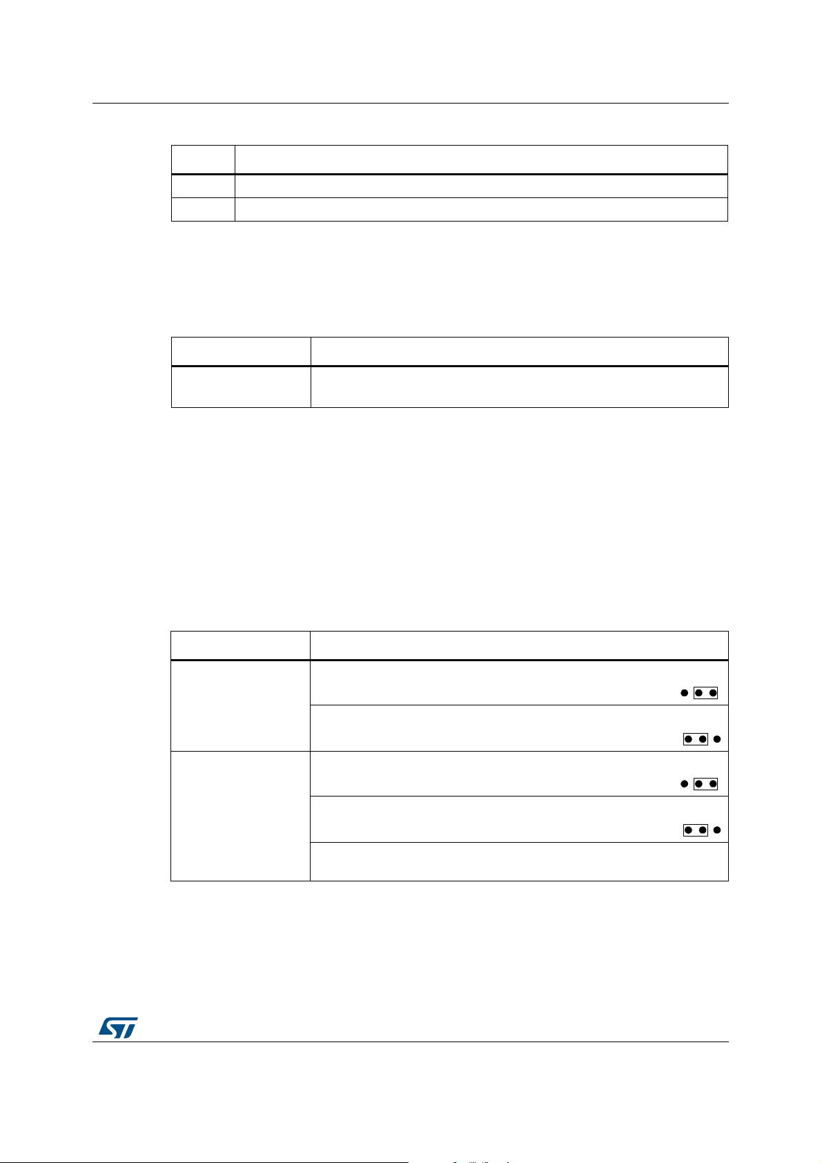
2.3 Clock source
Four clock sources are available on the STM3240G-EVAL evaluation board for
STM32F407IGH6 and RTC embedded:
• X1, 25 MHz crystal for Ethernet PHY with socket. It can be removed when clock is
provided by the MCU MCO pin
• X2, 26 MHz crystal for USB-OTG HS PHY
• X3, 32 kHz crystal for embedded RTC
• X4, 25 MHz crystal with socket for the,STM32F407IGH6 microcontroller (it can be
removed from socket when internal RC clock is used)
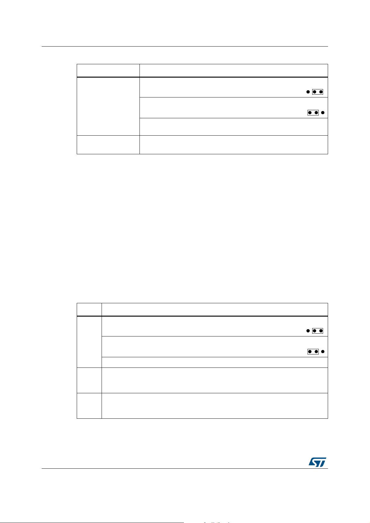
2.4 Reset source
The reset signal of the STM3240G-EVAL evaluation board is low active and the reset
sources include:
• Reset button B1
• Debugging tools from JTAG connector CN14 and trace connector CN13
• Daughterboard from CN3
• RS-232 connector CN916 for ISP
• ST-LINK/V2
2.5 Audio
The STM3240G-EVAL evaluation board enables stereo audio play and microphone
recording by an external headset connected on audio jack CN11. An audio DAC CS43L22 is
connected to both I2S2 port and a DAC channel and a microphone amplifier is connected to
the ADC of the STM32F407IGH6. CS43L22 can be configured via I2C1 and the external
PLL (U36) can be used to provide external clock which is connected to I2S_CKIN pin (PC9).
Note: To avoid speaker damage it is mandatory to connect the headphone to the board on CN11
during debug of audio code. When the program is stopped on a breakpoint, a DC voltage
may be applied to the speaker which induces power consumption incompatible with the
speaker.
Warning: Signal I2S_SD (PI3) is close to signal TCK/SWCLK of the
JTAG/SWD interface, so to avoid possible communication
issues on JTAG/SWD when the I2S interface is used the
recommendations are to:
1) Prefer usage of embedded ST-LINK/V2 to external tool
connected on CN14.
2) Configure PI3 GPIO in low speed (2 MHz or 10 MHz).
DocID022138 Rev 5 13/67
UM1461 Hardware layout and configuration
2.6 EEPROM
A 64 Kbit EEPROM is connected to the I2C1 bus of the STM32F407IGH6.
2.7 CAN
The STM3240G-EVAL evaluation board enables two channels of CAN2.0A/B compliant
CAN bus communication based on a 3.3V CAN transceiver on one DB9 connector (CN10).
The two CAN buses can be disconnected by jumpers from relevant STM32F407IGH6 I/Os
which are shared with FSMC and USB-OTG HS. Jumpers JP3 and JP10 must be refit to
enable CAN1 or CAN2 as listed in
Table 6.
High-speed, Standby and Slope Control modes are available and are selected by setting
jumper JP7.
Table 4. Audio related jumpers
Jumper Description
JP16 Description of JP16 is in Table 11 on page 16.
JP33 The microphone amplifier can be disabled when JP33 is fitted.Default setting: Not fitted
Table 5. EEPROM related jumper and solder bridge
Jumper Description
JP24
The EEPROM is in Write Protection mode when JP24 is not fitted.
Default Setting: Not fitted
Table 6. CAN-related jumpers
Jumper Description
JP3
To connect CAN1_TX to CAN transceiver, set JP3 as shown:
To connect CAN2_TX to CAN transceiver, set JP3 as shown:
JP10
To connect CAN1_RX to CAN transceiver, set JP10 as shown:
To connect CAN2_RX to CAN transceiver, set JP10 as shown:
PD0 and PB5 are disconnected from the CAN transceiver and used for
FSMC and USB_OTG_HS when jumper JP10 is not fitted (default setting).
321
321
321
321
Hardware layout and configuration UM1461
14/67 DocID022138 Rev 5
2.8 RS-232 and IrDA
Both RS-232 and IrDA communication are enabled by D-type, 9-pin RS-232 connectors
(CN16) and IrDA transceiver U11 which are connected to USART3 of the STM32F407IGH6
on the STM3240G-EVAL evaluation board.
The IrDA transceiver (TFDU6300) is not populated on STM3240G-EVAL evaluation board
from version C08. The version of the board is written on sticker on the bottom side of the
board (ex: MB786-C08). For boards version C08 or newer, it is possible to solder manually
the TDFU6300 on U11 footprint to support IrDA feature.
For ISP support, two signals are added on the RS-232 connector CN16:
• Bootloader_RESET (shared with CTS signal)
• Bootloader_BOOT0 (shared with DSR signal)
RS-232 or IrDA is selected via JP22. The position 2-3 of jumper JP22 is unused from
version C08 of the board. ISP is enabled via JP29 and JP34.
JP7
To enable the selected CAN transceiver to work in Standby mode,
set JP7 as shown:
To enable the selected CAN transceiver to work in High-speed
mode, set JP7 as shown (default setting):
To enable the selected CAN transceiver to work in Slope Control mode, do
not fit a jumper on JP7.
JP9
To enable the terminal resistor for the selected CAN, fit a jumper on JP9.
(Default setting: not fitted)
Table 6. CAN-related jumpers (continued)
Jumper Description
321
321
Table 7. RS-232 and IrDA related jumper
Jumper Description
JP22
To connect USART3_RX to IrDA transceiver and enable IrDA communication,
set JP22 as shown (this configuration is useless from version C08 of the board):
To connect USART3_RX to RS-232 transceiver and enable RS-232
communication, set JP22 as shown (Default setting):
To enable microSD card, which shares same I/Os with RS-232, JP22 is not fitted.
JP29
Bootloader_BOOT0 is managed by pin 6 of CN16 (RS-232 DSR signal) when JP29 is
closed. This configuration is used for boot loader application only.
Default setting: Not fitted.
JP34
Bootloader_RESET is managed by pin 8 of CN16 (RS-232 CTS signal) when JP34 is
fitted. This configuration is used for boot loader application only.
Default setting: Not fitted.
321
321
剩余66页未读,继续阅读
adams8432
- 粉丝: 1
- 资源: 9
上传资源 快速赚钱
- 我的内容管理 展开
- 我的资源 快来上传第一个资源
- 我的收益 登录查看自己的收益
- 我的积分 登录查看自己的积分
- 我的C币 登录后查看C币余额
- 我的收藏
- 我的下载
- 下载帮助
最新资源
- 多模态联合稀疏表示在视频目标跟踪中的应用
- Kubernetes资源管控与Gardener开源软件实践解析
- MPI集群监控与负载平衡策略
- 自动化PHP安全漏洞检测:静态代码分析与数据流方法
- 青苔数据CEO程永:技术生态与阿里云开放创新
- 制造业转型: HyperX引领企业上云策略
- 赵维五分享:航空工业电子采购上云实战与运维策略
- 单片机控制的LED点阵显示屏设计及其实现
- 驻云科技李俊涛:AI驱动的云上服务新趋势与挑战
- 6LoWPAN物联网边界路由器:设计与实现
- 猩便利工程师仲小玉:Terraform云资源管理最佳实践与团队协作
- 类差分度改进的互信息特征选择提升文本分类性能
- VERITAS与阿里云合作的混合云转型与数据保护方案
- 云制造中的生产线仿真模型设计与虚拟化研究
- 汪洋在PostgresChina2018分享:高可用 PostgreSQL 工具与架构设计
- 2018 PostgresChina大会:阿里云时空引擎Ganos在PostgreSQL中的创新应用与多模型存储
资源上传下载、课程学习等过程中有任何疑问或建议,欢迎提出宝贵意见哦~我们会及时处理!
点击此处反馈
安全验证
文档复制为VIP权益,开通VIP直接复制
信息提交成功