
4/16
General
Size 10 Size 16 Size 25 Size 25
1)
Size 32
Installation position Any, preferably horizontal
Ambient temperature range °F (°C) 0 ... 140 (0 ... 60)
Weight lbs 19.1 24.6 36.9 37.5 69.3
(kg) (8.7) (11.2) (16.8) (17) (31.5)
Hydraulic: measured at
p
= 1450 PSI (100 bar),
ν
= 148 SUS (32 mm
2
/s) and
t
= 140 °F (40 °C)
Operating pressure: PSI (bar) Size 10 Size 16 Size 25 Size 25
1)
Size 32
Pilot valve supply (min max) PSI (bar) 290 ... 4600 (20 ... 315)
Main valve max PSI 4600 5100 5100 3045 5100
P, A, B (bar) (315) (350) (350) (210) (350)
T-port with internal drain PSI (bar) <145 (<10) Static
T-port with external drain PSI 4600 3625 3625 3045 3625
(bar) (315) (250) (250) (210) (250)
Y-port PSI (bar) <145 (<10) Static
Nominal flow
Q
N
± 10 % at ∆
p
= 145 PSI (10 bar
2
) GPM (L/min) 6.60 (25)
13.2 (50) 33.0 (125) 58.1 (220)
26.4 (100) 52.8 (200) 92.4 (350) 132.1 (500) 158.5
(600)
Volumetric flow at main valve (max. permissible) GPM 44.9 122 230 264 423
(L/min) (170) (460) (870) (1000) (1600)
Control spool stroke (2nd stage) mm ± 3.5 ± 5 ± 6 ± 6 ± 9
Control volume flow X or Y at stepped GPM 1.7 3.6 6.7 6.7 7.0
input signal of 0 to 100 % 4600 PSI (315 bar) (L/min) (6.3) (13.7) (25.5) (25.5) (26.5)
Hydraulic fluid Petroleum oils (HM, HL, HLP)
Phosphate-ester fluids (HFD-R)
Fluid cleanliness: Maximum allowable fluid cleanliness level – class 16/13 –
18/15, according to ISO 4406. Therefore, we recommend
a filter with a minimum retention rate of
ß
10
≥ 75
Hydraulic fluid temperature range °F (°C) 50 ... 176 (10 ... 80) preferred 104 … 122 (40 … 50)
Viscosity range SUS (mm
2
/s) 97 ... 1760 (20 ... 380) preferred 141 … 208 (30 … 45)
Hysteresis % ≤ 0.2
Response sensitivity % ≤ 0.1
Electrical
Insulation (DIN 40 050) Exceeds NEMA class 4 (IP 65)
Voltage V DC 18 … 30
Power W 72
Electronic control Integral in valve, see below and page 6
Technical data (For applications outside these parameters, please consult us)
Command value: Reference potential at E and positive command value at D gives flow from P to A and B to T.
Reference potential at E and negative command value at D gives flow from P to B and A to T.
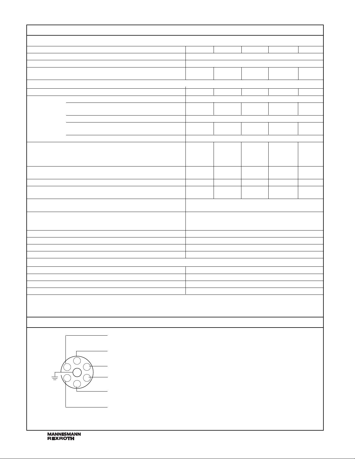
Electrical connection
1)
Model 4WRTE25 . . . 500.-3XH/ . . . (High Flow-design)
2)
∆
p
= Valve pressure differential in PSI (bar)
24 V (18 to 30 V DC)
0 V
Interlock 4 to 24 V to enable
Differential amplifier input
Command value ± 10 V
2)
Command value 0 V
Actual value ± 10 V
1)
A
D
B
C
F
E
Supply voltage
I
max
= 3 A
Surge load 4 A
1)
Signal >14 V indicates valve not ready (fault present
or not enabled correctly)
2)
Command of 0 to ±10 mA is available, specify
(SO) –280 under “further details”, R
i
= 1 kΩ
RA 29 082/06.98
剩余15页未读,继续阅读

jq1937
- 粉丝: 0
- 资源: 1
 我的内容管理
展开
我的内容管理
展开


最新资源
- 最优条件下三次B样条小波边缘检测算子研究
- 深入解析:wav文件格式结构
- JIRA系统配置指南:代理与SSL设置
- 入门必备:电阻电容识别全解析
- U盘制作启动盘:详细教程解决无光驱装系统难题
- Eclipse快捷键大全:提升开发效率的必备秘籍
- C++ Primer Plus中文版:深入学习C++编程必备
- Eclipse常用快捷键汇总与操作指南
- JavaScript作用域解析与面向对象基础
- 软通动力Java笔试题解析
- 自定义标签配置与使用指南
- Android Intent深度解析:组件通信与广播机制
- 增强MyEclipse代码提示功能设置教程
- x86下VMware环境中Openwrt编译与LuCI集成指南
- S3C2440A嵌入式终端电源管理系统设计探讨
- Intel DTCP-IP技术在数字家庭中的内容保护
资源上传下载、课程学习等过程中有任何疑问或建议,欢迎提出宝贵意见哦~我们会及时处理!
点击此处反馈


