"E1/E20和E2仿真器用户手册附加文件(RH850/F1L连接说明)"
需积分: 2 33 浏览量
更新于2023-11-23
收藏 1.03MB PDF 举报
E1/E20仿真器,E2仿真器用户手册附加文件(RH850/F1L连接说明)是由瑞萨电子公司发布的,适用于RH850系列和RH850/F1x系列设备。所有提供的信息包括产品和产品规格都代表了发布时的产品信息,可能会在不通知的情况下由瑞萨电子公司进行更改。用户应该通过瑞萨电子公司的官方渠道,比如公司网站,查看最新的信息。此外,用户需要注意,文档中关于电路、软件以及其他相关信息的描述只是为了说明半导体产品的操作和应用示例。用户需要对符合特定应用的设计、安装和操作进行充分的负责和评估。
E1/E20/E2 Emulator 2. Connecting the Emulator and User System
R20UT2452EJ1000 Rev.10.00 Page 9 of 48
Oct.09.20
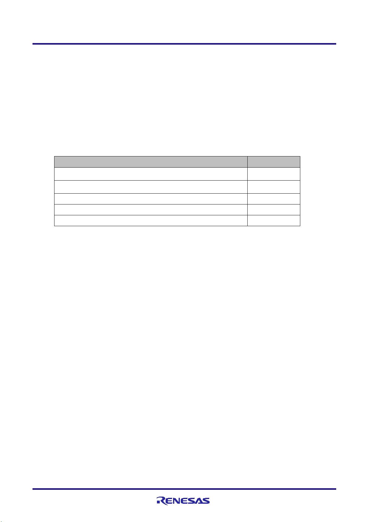
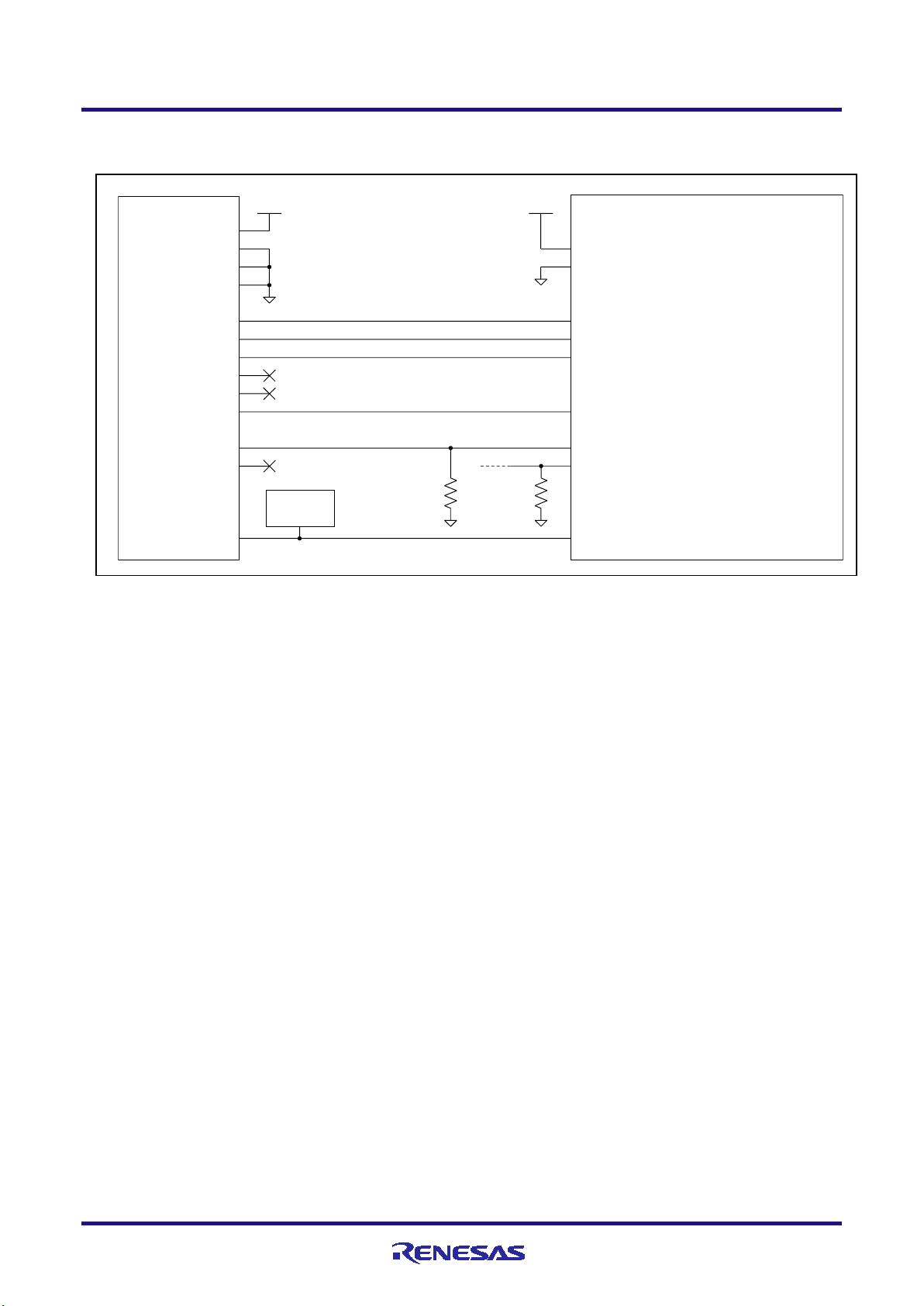
2.4 Examples of recommended connections between the connector and MCU
This section describes examples of recommended connections between the target MCU and interface circuit.
2.4.1 Example of recommended connections
Multiple recommended examples for connection are given in accord with the purposes for which the emulator is to be
used. Select the appropriate circuit with reference to the table shown below. Be sure to take the specifications of the
target device as well as measures to prevent noise into consideration when designing your circuit.
Purpose
Figure
Both debugging (4-pin LPD) and programming (1-wire UART or 2-wire
UART)
Figure 2-4
Both debugging (1-pin LPD or 4-pin LPD) and programming (1-wire UART
or 2-wire UART)
Figure 2-5
Both debugging (1-pin LPD) and programming (1-wire UART)
Figure 2-6
Only programming (1-wire UART or 2-wire UART)
Figure 2-7
Only programming (1-wire UART)
Figure 2-8
剩余47页未读,继续阅读
2023-09-26 上传
2018-03-13 上传
2023-09-26 上传
点击了解资源详情
2023-07-16 上传
2023-07-15 上传
2018-04-19 上传
2010-04-22 上传

weixin_45205499
- 粉丝: 0
- 资源: 6
 我的内容管理
展开
我的内容管理
展开


最新资源
- 基于Python和Opencv的车牌识别系统实现
- 我的代码小部件库:统计、MySQL操作与树结构功能
- React初学者入门指南:快速构建并部署你的第一个应用
- Oddish:夜潜CSGO皮肤,智能爬虫技术解析
- 利用REST HaProxy实现haproxy.cfg配置的HTTP接口化
- LeetCode用例构造实践:CMake和GoogleTest的应用
- 快速搭建vulhub靶场:简化docker-compose与vulhub-master下载
- 天秤座术语表:glossariolibras项目安装与使用指南
- 从Vercel到Firebase的全栈Amazon克隆项目指南
- ANU PK大楼Studio 1的3D声效和Ambisonic技术体验
- C#实现的鼠标事件功能演示
- 掌握DP-10:LeetCode超级掉蛋与爆破气球
- C与SDL开发的游戏如何编译至WebAssembly平台
- CastorDOC开源应用程序:文档管理功能与Alfresco集成
- LeetCode用例构造与计算机科学基础:数据结构与设计模式
- 通过travis-nightly-builder实现自动化API与Rake任务构建
