
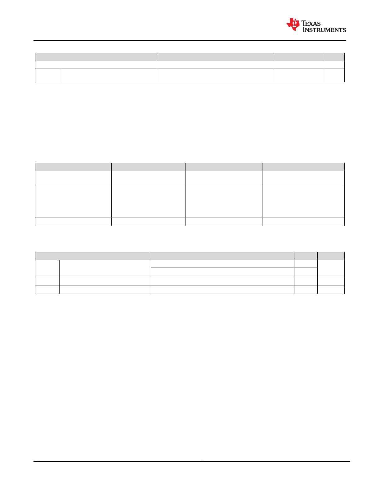
6.6 Insulation Specifications (continued)
PARAMETER TEST CONDITIONS VALUE UNIT
UL 1577 (Planned Certification Target)
V
ISO
Withstand isolation voltage
V
TEST
= V
ISO
= 5000 V
RMS
, t = 60 s (qualification); V
TEST
=
1.2 × V
ISO
= 6000 V
RMS
, t = 1 s (100% production)
5000 V
RMS
(1) Creepage and clearance requirements should be applied according to the specific equipment isolation standards of an application.
Care should be taken to maintain the creepage and clearance distance of a board design to ensure that the mounting pads of
the isolator on the printed-circuit board do not reduce this distance. Creepage and clearance on a printed-circuit board become
equal in certain cases. Techniques such as inserting grooves and/or ribs on a printed circuit board are used to help increase these
specifications.
(2) This coupler is suitable for safe electrical insulation only within the maximum operating ratings. Compliance with the safety ratings shall
be ensured by means of suitable protective circuits.
(3) Testing is carried out in air or oil to determine the intrinsic surge immunity of the isolation barrier.
(4) Apparent charge is electrical discharge caused by a partial discharge (pd).
(5) All pins on each side of the barrier tied together creating a two-terminal device
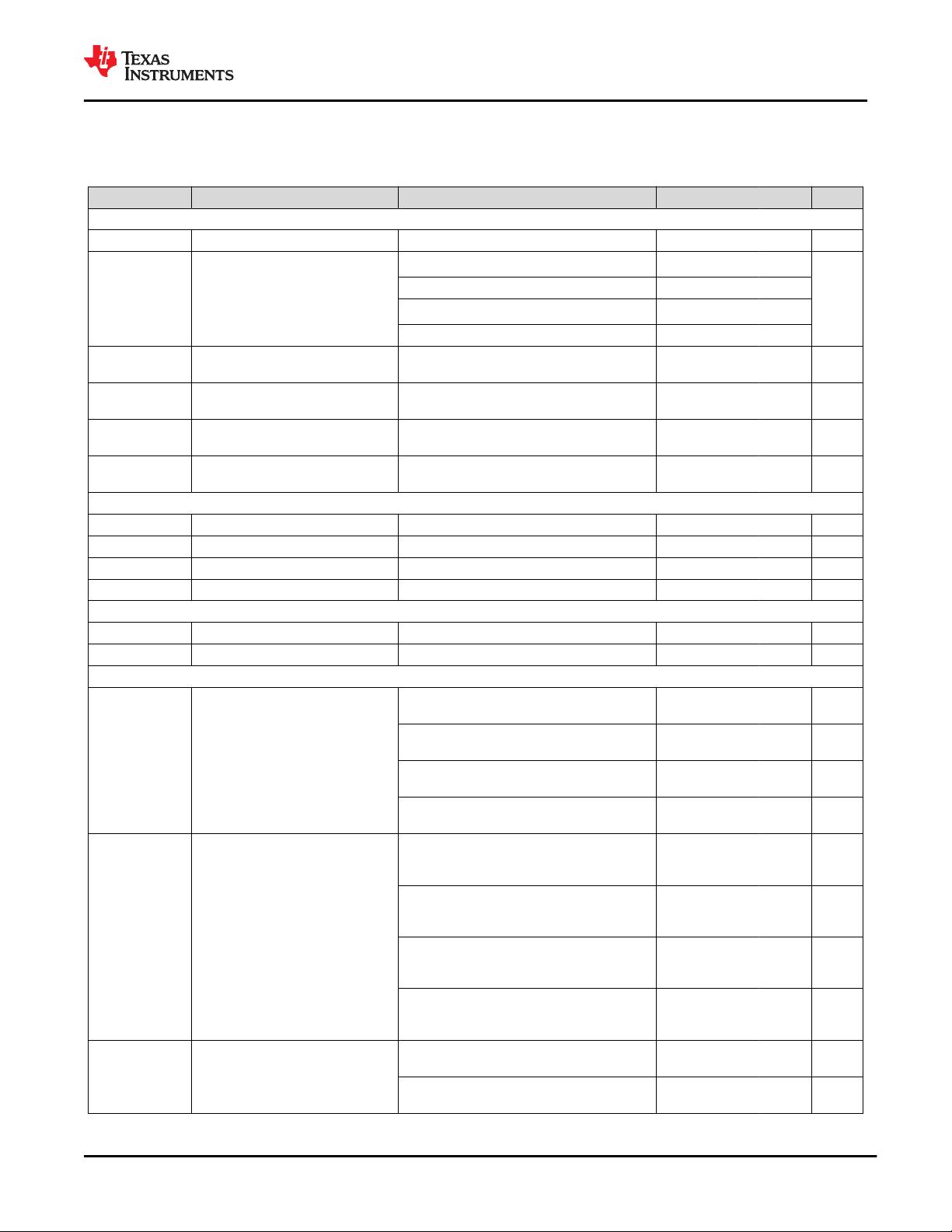
6.7 Safety-Related Certifications
VDE UL UL CQC
Plan to certify according to DIN V
VDE V 0884-11:2017- 01
Plan to certify according to IEC
60950-1 and IEC 62368-1
Plan to certify under UL 1577
Component Recognition Program
Plan to certify according to
GB4943.1-2011
Reinforced insulation
Maximum transient isolation voltage,
7071 V
PK
; Maximum repetitive peak
isolation voltage, 1697 V
PK
; Maximum
surge isolation voltage, 6250 VPK
Reinforced insulation per UL
60950-1-07+A1+A2, IEC 60950-1
2nd Ed.+A1+A2, UL 62368-1-14 and
IEC 62368-1 2nd Ed., 800 V
RMS
maximum working voltage (pollution
degree 2, material group I)
Single protection, 5000 V
RMS
Reinforced insulation, Altitude ≤ 5000 m,
Tropical Climate, 700 V
RMS
maximum
working voltage
Certificate number: (planned) Master contract number: (planned) File number: (planned) Certificate number: (planned)
6.8 Safety Limiting Values
Safety limiting intends to minimize potential damage to the isolation barrier upon failure of input or output circuitry.
PARAMETER TEST CONDITIONS MAX UNIT
I
S
Safety input current
(1)
R
θJA
= 57.5°C/W, V
I
= 5.5 V, T
J
= 150°C, T
A
= 25°C 395
mA
R
θJA
= 57.5°C/W, V
I
= 4.5 V, T
J
= 150°C, T
A
= 25°C 483
P
S
Safety input power R
θJA
= 57.5°C/W, T
J
= 150°C, T
A
= 25°C 2174 mW
T
S
Safety temperature
(1)
150 °C
(1) The maximum safety temperature, T
S
, has the same value as the maximum junction temperature, T
J
, specified for the device. The
I
S
and P
S
parameters represent the safety current and safety power respectively. The maximum limits of I
S
and P
S
should not be
exceeded. These limits vary with the ambient temperature, T
A
. The junction-to-air thermal resistance, R
θJA
, in the Thermal Information
table is that of a device installed on a high-K test board for leaded surface-mount packages. Use these equations to calculate the value
for each parameter: T
J
= T
A
+ R
θJA
× P, where P is the power dissipated in the device. T
J(max)
= T
S
= T
A
+ R
θJA
× P
S
, where T
J(max)
is
the maximum allowed junction temperature. P
S
= I
S
× V
I
, where V
I
is the maximum input voltage.
UCC12051-Q1
SNVSBY2A – JANUARY 2021 – REVISED JUNE 2021
www.ti.com
6 Submit Document Feedback
Copyright © 2021 Texas Instruments Incorporated
Product Folder Links: UCC12051-Q1
剩余32页未读,继续阅读

不觉明了
- 粉丝: 3285
- 资源: 5614
 我的内容管理
收起
我的内容管理
收起
- 我的资源
快来上传第一个资源
 我的收益 登录查看自己的收益
 我的积分
登录查看自己的积分
我的积分
登录查看自己的积分
 我的C币
登录后查看C币余额
我的C币
登录后查看C币余额
 我的收藏
我的收藏  我的下载
我的下载  下载帮助
下载帮助

会员权益专享


最新资源
- 电力电子与电力传动专业《电子技术基础》期末考试试题
- 电力电子技术期末考试题:电力客户与服务管理专业
- 电力系统自动化《电力电子技术》期末考卷习题精选
- 电力系统自动化专业《电力电子技术》期末考试试题
- 电子信息专业《电子技术》期末考试试题解析
- 电子与信息技术专业《电子技术》期末考试试题概览
- 电子信息工程《电子技术》期末考卷习题集
- 电子信息工程专业《电子技术》期末考试试题解析
- 电子信息工程《电工与电子技术》期末考试试题解析
- 电子信息工程专业《电子技术基础》期末考试计算题解析
- 电子技术期末考试题试卷(试卷B)——电子技术应用专业
- 电子科技专业《电力电子技术》期末考试填空题精选
- 2020-21秋《电力电子技术》电机电器智能化期末试题解析
- 电气工程及其自动化专业《电子技术》期末考试题(卷六)
- 电气工程专业《电子技术基础》期末考试试题解析
- 电气自动化专业《电子技术》期末考试试题解析
资源上传下载、课程学习等过程中有任何疑问或建议,欢迎提出宝贵意见哦~我们会及时处理!
点击此处反馈


