C#集合基础:数组、ArrayList与泛型详解
需积分: 14 41 浏览量
更新于2024-07-26
收藏 1.13MB DOC 举报
C#中的数组是本章学习的重要部分,它是基础的数据结构,用于存储一系列相同类型的元素。在C#中,数组可以是一维、二维甚至多维,包括简单数组和复杂数组。数组申明时需要指定元素类型和大小,例如`int[] myArray = new int[10];`表示创建了一个包含10个整数的数组。
Array类是.NET框架提供的内置类,提供了对数组操作的一些基本功能,如排序、查找等。然而,ArrayList虽然也是数组的一种实现,但它提供了动态扩容的能力,即可以在运行时添加或删除元素,这对于处理不确定大小的数据集合非常方便。
泛型是C#的一大特色,它允许你在编写代码时指定类型参数,从而创建可以处理多种数据类型的通用组件。泛型的主要特征包括类型参数化、类型推断和类型安全。通过泛型类、接口和方法的编写,我们可以创建更灵活且具有类型安全的代码,避免了硬编码类型带来的局限性。
集合接口是.NET框架中定义的一组接口,用于统一描述各种集合类型的行为。常见的接口有ICollection、IEnumerable和IList等,它们提供了诸如添加、删除、遍历等操作。泛型集合如List<T>和Dictionary<TKey, TValue>是实际应用中常用的泛型接口实现。
枚举是另一种重要的数据类型,用于定义一组命名的常量,便于程序理解和管理。它可以提供清晰的文档和易于维护的代码。在本章,通过网吧管理和专业课程管理两个实例,学生将学习如何声明和使用枚举。
本章内容涵盖了数组的基础概念和操作,以及更高级的主题如泛型和集合接口,这些都是C#编程中不可或缺的知识点。通过实例学习,学生能够掌握数组的动态和静态维度,理解ArrayList和Array的区别,掌握泛型的使用及其带来的优势,同时了解接口和抽象类与枚举的异同。掌握这些内容后,学生将对C#中的集合数据结构有全面的认识,为后续编程实践打下坚实的基础。
B)!6#岁6
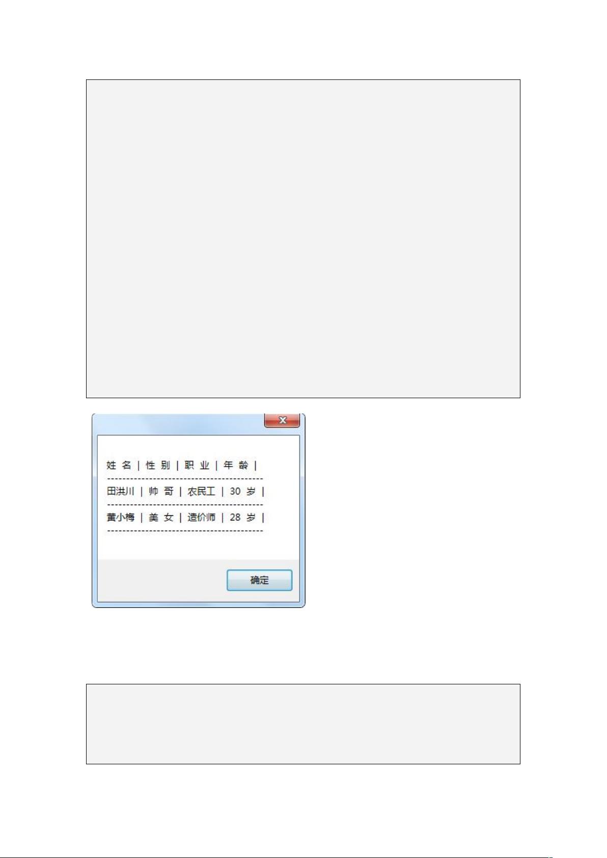
下面读取出上面二维数组的值
B)?%&,".获取第一维中元素项数
JB)?%&,.获取第二维中元素项数
+(A3:=+(A3:,.用一个可变字符串对象来接收循环中的值
循环第一维
0),"122.
接着循环第二维
0),"1J22.
将数组的当前项加一些空格和一根竖线的字符串加到可变字符串=的结尾
=IBB:,B)!26K6.
$
注意下面这句是关键,这句规定了一行完整的信息读取完了就换行,并用5555来分隔
=IBB:,6L55555555555555555555555555555555555555555L6.
$
'()*+&),=-)+,..
$
执行后效果如图 5-7
图 5-7
多维数组也一样,一旦数组声明之后,就不能修改其维(秩)数了。如果事先知道元
素的值,也可以使用数组索引器来初始化二维数组。在初始化数组时,使用一个外层的花
括号,每一行用包含在外层花括号中的内层花括号来初始化。
!
!!$!
!!$!
!#!$!
$


剩余63页未读,继续阅读
2014-06-29 上传
2022-07-25 上传
2020-10-26 上传
2023-06-07 上传
2023-06-07 上传
2023-06-07 上传
2023-06-02 上传

wzw312
- 粉丝: 0
- 资源: 1
 我的内容管理
展开
我的内容管理
展开


最新资源
- 减去图像均值matlab代码-Cropmeasure:测量作物绿色度的简单代码,不太可能对任何人有用
- Hewi_ios:它是在项目实践期间开发的ios小部件应用程序。
- IT_Logger:ReactRedux应用程序可跟踪IT部门的任务和问题
- eks-microservice:AWS EKS Microservice-易于设置
- ANNOgesic-1.0.20-py3-none-any.whl.zip
- idk
- 使用MFC打印和打印预览OpenGL
- computationalIntelligence:计算智能讲座练习@ ZHAW 2015
- weather_crawl:抓取工具收集韩国的天气信息
- project-fusion:Boilerplate Web入门工具包,既实用又灵活。 旨在使开发人员快速启动并运行并保持敏捷。 高度自动化和开箱即用的支持ES6,JSPM,Gulp,Babel,Karma和Mocha。 能够使用SC5样式指南和KSS语法自动生成样式指南。 使用Backstop jSCSS回归测试。 Nunjucks模板。 基于git提交历史记录和注释的自动发布(颠簸重新推荐,changelog文件生成和github自动发布)。 使用ESDoc自动生成Javascript文档。 模块化设
- Web_HC_ZL_Javascript_Slider:网页赫彩中坜JS应用轮播套件
- ALGOpractice
- 创建屏幕-Android UI布局和控件
- 旅游公司网站模版
- DMOJJava解决方案
- java长途客车网上售票系统分析与设计(含毕业论文和sql文件)
