TI bq76920: 电池监控与保护系统
需积分: 11 55 浏览量
更新于2024-06-30
4
收藏 2.12MB PDF 举报
"TI-BQ76920.pdf 是一份技术文档,主要介绍TI公司的一款电池管理系统芯片——bq769x0系列,包括bq76920、bq76930和bq76940。这款芯片主要用于锂离子和磷酸铁锂电池的应用,具备模拟前端(AFE)监控功能和硬件保护特性,能够实现对电池组的全面监控和保护。"
TI公司的bq769x0系列芯片是专为锂离子和磷酸铁锂电池设计的高集成度电池管理系统。这个系列的主要特点是:
1. **模拟前端(AFE)监控特性**:该芯片具有纯数字接口,可以测量电池电压、芯片温度以及外部热敏电阻的温度。它还内置了一个独立的ADC,用于测量电池组的电流,执行库仑计数,从而精确跟踪电池容量。
2. **硬件保护功能**:bq769x0提供了多种硬件保护机制,如放电过流保护(OCD)、放电短路保护(SCD)、过压保护(OV)、欠压保护(UV)以及对次级保护器故障的检测,确保电池在各种条件下都能安全运行。
3. **附加特性**:集成了电池均衡功能,通过内部场效应晶体管(FET)来平衡电池组中的单体电池电压。此外,芯片还包含了充电和放电的低侧N沟道FET驱动器,能直接控制电池的充放电过程。它还具有报警中断功能,当电池状态异常时,可以通过ALERT引脚向主机微控制器发送中断信号。工作电压可以选择2.5V或3V。
4. **系统连接**:从给出的部分内容可以看到,芯片有多个关键引脚,如BAT、VC1-VC5、VSS、SCL、SDA、CHG、DSG、REGSRC、REGOUT、SRN、SRP、VC0、CAP1、TS1和Cf等,这些引脚分别对应电池连接、I2C通信、充电状态、电源管理以及其他关键功能。
5. **应用范围**:bq769x0系列适用于需要精细电池管理的系统,如电动汽车、储能设备、便携式电子设备等,能够提供安全可靠的电池管理解决方案。
这份文档详细介绍了bq769x0系列芯片的特性和功能,对于设计和实施锂离子或磷酸铁锂电池系统的工程师来说是一份重要的参考资料。用户可以通过TI提供的样片、购买和技术支持等服务进一步了解和评估该产品。
12
bq76920, bq76930, bq76940
ZHCSCE2F –OCTOBER 2013–REVISED NOVEMBER 2015
www.ti.com.cn
提交文档反馈意见
产品主页链接: bq76920 bq76930 bq76940
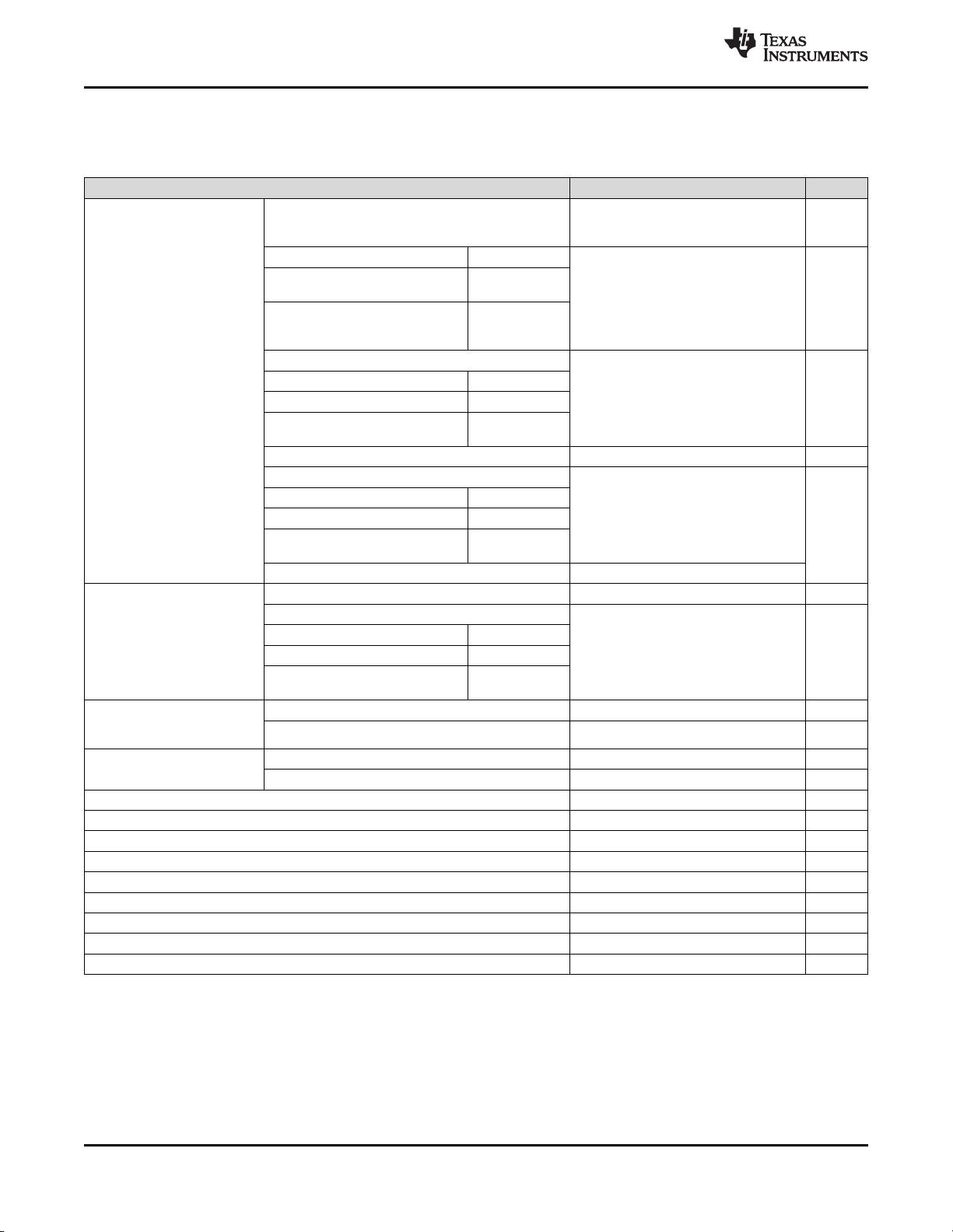
Electrical Specifications 版权 © 2013–2015, Texas Instruments Incorporated
Recommended Operating Conditions (continued)
Over-operating free-air temperature range (unless otherwise noted). See 节 8.1.1 for more information on cell configurations.
All voltages are relative to VSS, except "Cell input differential."
MIN TYP MAX UNIT
V
IN
Input voltage range
Cell input pins, differential (VCn–VCn–1) where n =
1..15/10/5 (bq76940/bq76930/bq76920, respectively),
in-use cells only
2 5 V
(VCn–VSS) where n = 1..5 bq76920
0 5 × n V
(VCn–VSS) where n = 1..5,
(VCn–VC5x) where n = 6..10
bq76930
(VCn–VSS) where n = 1..5,
(VCn–VC5x) where n = 6..10,
(VCn–VC10x) where n = 11..15
bq76940
SRP
–10 10 mV
(VC0–VSS) bq76920
(VC0–VSS), (VC5b–VC5x) bq76930
(VC0–VSS), (VC5b–VC5x),
(VC10b–VC10x)
bq76940
SRN –200 200 mV
SCL, SDA
0 3.6
V
(TS1–VSS) bq76920
(TS1–VSS), (TS2–VC5x) bq76930
(TS1–VSS), (TS2–VC5x),
(TS3–VC10x)
bq76940
REGSRC 6 25
V
OUT
Output voltage
range
CHG, DSG 0 16 V
REGOUT, ALERT
0 3.6 V
(CAP1–VSS) bq76920
(CAP1–VSS), (CAP2–VC5x) bq76930
(CAP1–VSS), (CAP2–VC5x),
(CAP3–VC10x)
bq76940
I
CB
Cell balancing
current (internal, per
cell)
bq76920 0 50 mA
bq76930, bq76940 0 5 mA
R
C
External cell input
resistance
bq76920 40 100 1K Ω
bq76930, bq76940 500 1K 1K Ω
C
C
External cell input capacitance 0.1 1 10 µF
R
f
External supply filter resistance 40 100 1K Ω
C
f
External supply filter capacitance 1 10 40 µF
R
FILT
Sense resistor filter resistance 100 1K Ω
R
ALERT
ALERT pin to VSS resistor 1M Ω
C
L
REGOUT loading capacitance 1 4.7 µF
C
CAP
REGSRC, CAP1, CAP2, and CAP3 output capacitance 1 µF
R
TS
External thermistor nominal resistance (103AT) at 25ºC 10K Ω
T
OPR
Operating free-air temperature –40 85 °C
剩余66页未读,继续阅读
2022-11-30 上传
2022-11-12 上传
2022-10-29 上传
2022-10-29 上传
2022-10-29 上传
2022-10-29 上传
2022-11-16 上传
2022-10-29 上传
2022-10-29 上传

不觉明了
- 粉丝: 7490
- 资源: 5764
 我的内容管理
展开
我的内容管理
展开


最新资源
- playn-swt-java-1.8.zip
- smartdove:SMARTDOVE PHPLaravel SDK
- 易语言外形框模仿进度条
- 功能强大的万年历源码 v1.0
- Craftassist:Minecraft中的虚拟助手机器人
- RYUTO:龙人
- My-Personal-Pertfolio-Project
- Disk2vhd安装包
- 7yuvrj.rar
- uploadfiles-maven-plugin-1.0.1.zip
- HDP-GPL-3.1.4.0-centos7-gpl.tar.gz
- 222个科技、数字产品相关图标 .fig素材下载
- aws-k8s-provision:轻松地在AWS上部署kubernetes
- microbium-app:吸引新世界
- 直流电机原理动画.zip
- ApkToolkit.zip
