STC89C52RC单片机八路抢答器设计:功耗低,响应精准
版权申诉
113 浏览量
更新于2024-06-24
收藏 660KB DOC 举报
本文档主要介绍了基于51单片机(STC89C52RC)设计的一款八路抢答器系统。设计的目标是为了提供一个易于使用、高区分度的抢答设备,以适应日益增多的各种竞赛需求。该系统利用单片机的低功耗、智能化特性,实现了以下几个关键功能:
1. **设计目标**:
- 基本功能:支持八路抢答,能够实时显示哪一组率先按下抢答键,确保比赛公平。
- 技术参数:具备限时回答功能,确保在规定时间内答题,超出则不计分;系统具有开始键控制、犯规检测、时间锁定和自动复位机制。
2. **硬件设计**:
- **系统架构**:设计包括电源管理、单片机最小系统、数码管显示电路、按键输入电路以及报警与指示电路。
- **电源设计**:保证系统的稳定运行,可能采用了稳压电源或电池供电。
- **数码管显示电路**:采用共阴数码管,通过单片机控制,清晰地显示抢答路数。
- **按键输入电路**:使用开关作为键盘输入,接收选手的抢答操作。
- **报警与指示电路**:包括蜂鸣器用于提示和错误指示,确保操作员和参赛者了解状态。
3. **软件设计**:
- **组成部分**:软件由延时子函数、初始化、开始键扫描、抢答按键扫描、显示、时间调整、定时器中断处理和主函数等模块构成。
- **功能实现**:通过定时器/计数器实现时间控制,确保计时准确;延时子函数确保响应速度;初始化子函数设置系统初始状态;开始键和抢答键的扫描确保抢答规则的有效执行。
4. **软件仿真**:
- 使用PROTEUS进行仿真,通过图形化界面展示系统的工作流程,验证硬件和软件设计的正确性。
综上,该设计通过STC89C52RC单片机为核心,构建了一个功能完备、操作简便且可靠稳定的八路抢答器系统,体现了单片机在实际应用中的优势。无论是硬件设计还是软件编程,都充分考虑了比赛的公正性和实用性,是一次典型的嵌入式系统开发实践。
since defined. support system management server and consumption POS machine automatically on Shi on Shi frequency can set, support parameter automatically Xia biography, and personnel automatically Xia biography, and task query, function, support variety report: trading summary table, and purchase statistics, and filling buckle adjustable statistics, and withdrawals statistics, and Back to statistical tables, entry tables, manually consumption Details tab, employee consumption summary accounting and management requirements. (3.) parking lot management systemRehabilitation Centre underground parking lots, and locations in the medical Building basement, second floor. Parking management system is a set of video surveillance, access management, parking management, leading spaces, vehicle access control and integrated system management in one. Car park management system and security monitoring system, alarm linkage system, different settings in the import and export control system control box, parking control system in comprehensive management of comprehensive medical building security monitoring center, audio and video surveillance, alarm systems and other new Exchange each other, form a comprehensive, convenient and efficient Ta systems. Parking entrance equipped with image acquisition, comparison system, vehicle access and egress will be automatically collected and stored image information of the vehicle, and according to the card number automatically from the database to bring up the corresponding vehicle information and accurate comparison of the pictures confirm that prevent a vehicle from being stolen. Acquisition of image information is automatically saved for later, and verification. Parking out entrance has alarm device, once access entrance location occurred accident situation, parking site management personnel can timely triggered alarm device, will
4
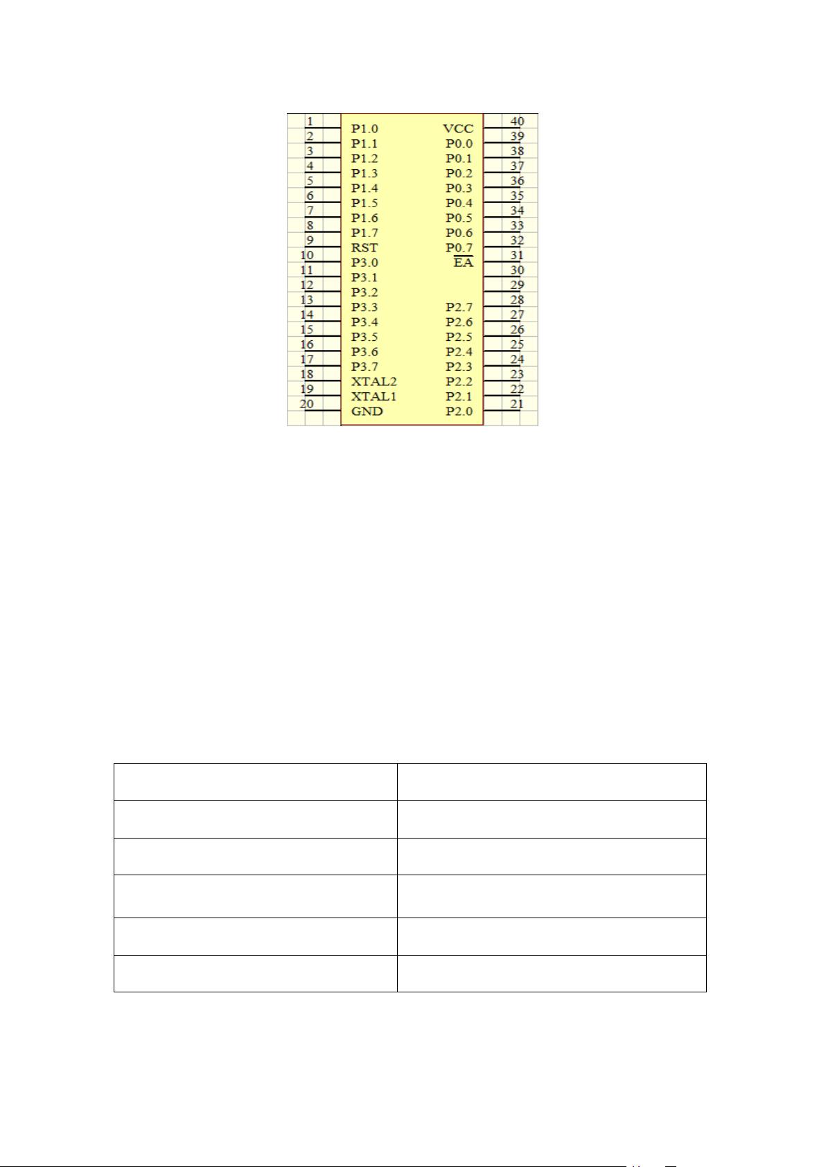
图 2-2-1 STC89C52RC 单片机
STC89C52RC 本身内含 40 个引脚,32 个外部双向输入/输出(I/O)端口,同时内
含 2 个外中端口,3 个 16 位可编程定时计数器,2 个全双工串行通信口,STC89C51RC
可以按照常规方法进行编程,但不可以在线编程。其将通用的微处理器和 Flash 存储器
结合在一起,特别是可反复擦写的 Flash 存储器可有效地降低开发成本。
STC89C52RC 的主要特性如下表所示:
表 2-2-1 STC89C52RC 主要功能描述
STC89C52RC 为 40 脚双列直插封装的 8 位通用微处理器,采用工业标准
兼容 MCS—51 指令系统
32 个可编程 I/O 线
4k 字节可编程闪烁存储器
可编程 UARL 通道
三个 16 位可编程定时/计数器中断
时钟频率 0-24MHz
2 个外部中断源,共 8 个中断源
256×8bit 内部 RAM
2 个读写中断口线
可直接驱动 LED
软件设置睡眠和唤醒功能
低功耗空闲和掉电模式


剩余60页未读,继续阅读
134 浏览量
145 浏览量
900 浏览量
241 浏览量
370 浏览量
2021-10-02 上传
118 浏览量
140 浏览量

老帽爬新坡
- 粉丝: 101
 我的内容管理
展开
我的内容管理
展开


最新资源
- 获取最新libiconv解压包的技巧
- 3DS Max2012模型导出插件PandaDirectXMaxExporter介绍
- Delphi7实现微信扫码支付模式二及统一下单功能
- 基于apicloud的返利网站源码开发教程
- 提升Mac OS X输入效率的InputCtrlN-crx插件
- VC 2008实现鼠标控制操作的C++源代码解析
- javadbf-0.4.0中文支持升级与测试代码分享
- 全面覆盖Web开发的JQuery核心文件压缩包
- NOTE3 N9009 EFS备份还原工具使用教程
- VC++实现Flash动画播放功能的源码解析与应用
- POI依赖包列表:将PPT转换为图片的必备工具
- Cursory-crx插件:一键提取文章重点摘要
- 小区水电管理系统Delphi代码实现及SQL2000数据库应用
- WPF开发简易记账软件安装版:收入支出记录与检索
- 全案例演示:HTML5+CSS3+JavaScript网页设计源代码与素材
- Java实现ID3算法详解及代码示例