VNH5019ATR-E:汽车级全集成H桥电机驱动器
需积分: 0 81 浏览量
更新于2024-06-25
收藏 464KB PDF 举报
"VNH5019ATR-E是一款汽车级全集成H桥电机驱动器,具备多种保护功能和高效能特性。"
VNH5019ATR-E是一款由意法半导体(STMicroelectronics)制造的高性能电机驱动芯片,特别适用于各种汽车应用。这款芯片设计紧凑,集成了一个双路单片高压侧驱动器和两个低压侧开关,能够提供高达30A的输出电流。其核心技术是采用ST的专有VIPower® M0技术,将真正的功率MOSFET与智能信号/保护电路整合在同一硅片上,确保了高效和可靠的电机控制。
该器件的关键特点包括:
1. 环保封装:符合ECOPACK®标准,无铅且符合RoHS规定,对环境友好。
2. 汽车级认证:遵循AEC(汽车电子委员会)指导原则,确保在严苛的汽车环境中稳定工作。
3. 输入兼容性:3V CMOS兼容输入,便于与各种微控制器接口。
4. 保护功能:具有欠压和过压关断保护,以及高侧和低侧热关断保护,防止过热损坏。
5. 交叉导通防护:防止高侧和低侧开关同时导通,避免功率损失和潜在损坏。
6. 电流限制:内置电流限制功能,保护电机免受过载影响。
7. 低功耗待机:在非工作状态下,功耗极低,提高了系统效率。
8. PWM操作:支持高达20kHz的脉宽调制(PWM)操作,实现精确的电机速度控制。
9. 保护机制:具备地线丢失和VCC丢失保护,增强系统稳定性。
10. 电流感应输出:输出电流与电机电流成比例,方便实时监控电机状态。
11. 反极性保护:内置电荷泵输出,用于防止电源极性反接造成的损坏。
12. 短路保护:输出端口保护设计,可抵御接地和短路到VCC的情况。
VNH5019ATR-E是一款强大且安全的电机驱动解决方案,适用于需要高效率、高可靠性和多重保护措施的汽车及工业应用。其独特的设计和全面的保护特性使其在各种电机控制场景中表现出色,确保了系统的稳定运行和长期耐用性。
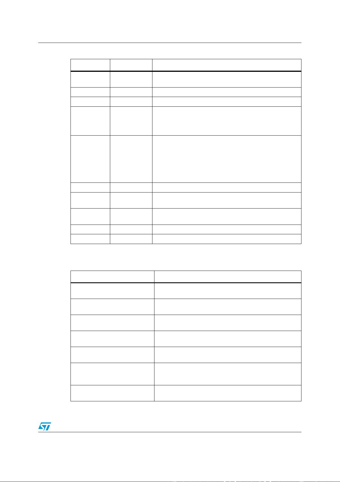
VNH5019A-E Block diagram and pin description
Doc ID 15701 Rev 9 7/37
)
6 CS_DIS
Active high CMOS compatible pin to disable the current sense
pin
4IN
A
Clockwise input. CMOS compatible
7 PWM PWM input. CMOS compatible.
8CS
Output of current sense. This output delivers a current
proportional to the motor current, if CS_DIS is low or left open.
The information can be read back as an analog voltage across
an external resistor.
9EN
B
/DIAG
B
Status of high-side and low-side switches B; Open drain output.
This pin must be connected to an external pull up resistor. When
externally pulled low, it disables half-bridge B. In case of fault
detection (thermal shutdown of a high-side FET or excessive
ON-state voltage drop across a low-side FET), this pin is pulled
low by the device (see Table 13: Truth table in fault conditions
(detected on OUTA).
10 IN
B
Counter clockwise input. CMOS compatible
11 CP
Connection to the gate of the external MOS used for the reverse
battery protection
15, 16, 21
OUT
B,
Heat Slug3
Source of high-side switch B / drain of low-side switch B, power
connection to the motor
26, 27, 28 GND
A
Source of low-side switch A and power ground
(1)
18, 19, 20 GND
B
Source of low-side switch B and power ground
(1)
1. GNDA and GNDB must be externally connected together
Table 3. Block descriptions
(1)
Name Description
Logic control
Allows the turn-on and the turn-off of the high-side and the
low-side switches according to the Table 12.
Overvoltage + undervoltage
Shut down the device outside the range [4.5 V to 24 V] for the
battery voltage.
High-side, low-side and clamp
voltage
Protect the high-side and the low-side switches from the
high-voltage on the battery line in all configuration for the motor.
High-side and low-side driver
Drive the gate of the concerned switch to allow a proper R
DS(on)
for the leg of the bridge.
Linear current limiter
Limits the motor current, by reducing the high-side switch
gate-source voltage when short-circuit to ground occurs.
High-side and low-side
overtemperature protection
In case of short-circuit with the increase of the junction’s
temperature, it shuts down the concerned driver to prevent its
degradation and to protect the die.
Low-side overload detector
Detects when low-side current exceeds shutdown current and
latches off the concerned low-side.
Table 2. Pin definitions and functions (continued)
Pin Symbol Function

剩余36页未读,继续阅读
2018-05-16 上传
2023-06-10 上传
2023-06-10 上传
2024-10-31 上传
2024-10-31 上传
2021-05-03 上传
2021-05-19 上传
183 浏览量
2021-03-20 上传

白中白中白xixi
- 粉丝: 0
- 资源: 4
 我的内容管理
展开
我的内容管理
展开


最新资源
- character,断点续传c语言源码,c语言
- konwerter
- psk和2dpsk.zip
- 方法
- 转移函数到状态空间表示:[F,h,c,d]=tfn2ss(N,D) 在这个表示中输出 y=x1-matlab开发
- rocFFT:ROCm的下一代FFT实现
- edgedetection,电脑关机源码c语言,c语言
- elasticsearch-analysis-hao:一个非常hao用的elasticsearch(es)中文分词器插件
- rest-example:REST应用程序示例
- [其他类别]php 汉字转拼音_hzp.rar
- WFG-Gaming-Shop:世界著名游戏在线游戏商店
- 安卓小熊录屏V2.4.6.2 支持1080P录制.txt打包整理.zip
- backup:数据库备份
- fx-master:依赖注入框架Fx的原始中文说明
- BPpidc,c语言中补码和源码,c语言
- 函数逼近的无界分辨率:连续函数针对变化的输出和增加的参数化维度进行了优化-matlab开发
