CC3100 SimpleLink Wi-Fi与物联网解决方案
需积分: 9 149 浏览量
更新于2024-06-28
5
收藏 2.08MB PDF 举报
"TI-CC3100是一款由德州仪器(TI)推出的SimpleLink Wi-Fi和物联网解决方案,适用于与微控制器(MCU)配合使用的应用。该器件集成了Wi-Fi网络处理器子系统、电源管理子系统,以及802.11b/g/n射频、基带和媒介访问控制(MAC)功能。它还包括了Wi-Fi驱动程序、TCP/IP堆栈,并且支持多种互联网协议。CC3100具有低外部主机驱动器封装尺寸,易于与各种MCU或ASIC对接,并提供了高效能的加密引擎,确保WPA2个人和企业级的安全性。此外,它还具备智能配置功能,如SmartConfig和WPS2,以及先进的低功耗模式。"
CC3100的主要特性包括其优秀的接收灵敏度,如-95.7dBm@1DSSS和-74.0dBm@54OFDM,这使得设备在无线通信中能接收更弱的信号。它内置的Wi-Fi网络处理器子系统能够处理大部分Wi-Fi和互联网协议,减轻了外部MCU的负担。器件内嵌的ROM包含了Wi-Fi驱动程序和多种互联网协议,简化了开发过程。CC3100提供了SPI和UART接口,可以方便地与各种微控制器进行通信。
该解决方案支持8个同时TCP或UDP,2个同时TLS和SSL插槽,满足多连接需求。电源管理子系统则支持宽范围的电源电压,如VBAT宽电压模式的2.1至3.6V,以及预稳压1.85V模式,有助于优化能耗。其低功耗特性如休眠模式下仅4μA的电流消耗,以及低功耗深度睡眠(LPDS)模式下的115μA,使得设备在保持连接的同时,实现了极低的功耗。
CC3100的加密引擎支持256位AES加密,确保了在TLS和SSL连接下的安全性。它还支持多种操作模式,如基站、访问点(AP)和Wi-Fi Direct,适应不同的网络环境。此外,SmartConfig技术使得设备能够便捷地连接到网络,而WPS2功能则简化了设备的配对过程。
TI-CC3100是一款集成度高、功能强大且低功耗的Wi-Fi解决方案,专为物联网应用设计,旨在提供无缝的Wi-Fi连接体验,同时兼顾了开发简便性和运行效率。对于那些需要在产品中整合Wi-Fi功能的嵌入式系统开发者来说,CC3100是一个理想的选项。
CC3100
ZHCSCJ6C –JUNE 2013–REVISED JUNE 2014
www.ti.com.cn
4 Specifications
All measurements are referenced at the device pins, unless otherwise indicated. All specifications are over
process and voltage, unless otherwise indicated.
4.1 Absolute Maximum Ratings
over operating free-air temperature range (unless otherwise noted)
PARAMETERS PINS MIN MAX UNIT
V
BAT
and V
IO
37, 39, 44 –0.5 3.8 V
V
IO
-V
BAT
(differential) 10, 54 0.0 V
Digital inputs –0.5 V
IO
+ 0.5 V
RF pins –0.5 2.1 V
Analog pins (XTAL) –0.5 2.1 V
Operating temperature range (T
A
) –40 +85 °C
4.2 Handling Ratings
MIN MAX UNIT
T
stg
Storage temperature range –55 +125 °C
Human body model (HBM), per ANSI/ESDA/JEDEC
–2000 +2000 V
JS-001, all pins
(1)
V
ESD
Electrostatic discharge
Charged device model (CDM), per JEDEC
–500 +500 V
specification JESD22-C101, all pins
(2)
(1) JEDEC document JEP155 states that 500-V HBM allows safe manufacturing with a standard ESD control process.
(2) JEDEC document JEP157 states that 250-V CDM allows safe manufacturing with a standard ESD control process.
4.3 Power-On Hours
CONDITIONS POH
T
Ambient
up to 85°C, assuming 20% active mode and 80% sleep mode 17,500
(1)
(1) The CC3100 device can be operated reliably for 10 years.
4.4 Recommended Operating Conditions
over operating free-air temperature range (unless otherwise noted)
(1)
PARAMETERS PINS CONDITIONS
(2) (3)
MIN TYP MAX UNIT
V
BAT
, V
IO
(shorted to V
BAT
) 10, 37, 39, Direct battery connection 2.1 3.3 3.6 V
44, 54
V
BAT
, V
IO
(shorted to V
BAT
) 10, 37, 39, Preregulated 1.85 V 1.76 1.85 1.9 V
44, 54
Ambient thermal slew –20 20 °C/minute
(1) Operating temperature is limited by crystal frequency variation.
(2) To ensure WLAN performance, ripple on the 2.1- to 3.3-V supply must be less than ±300 mV.
(3) To ensure WLAN performance, ripple on the 1.85-V supply must be less than 2% (±40 mV).
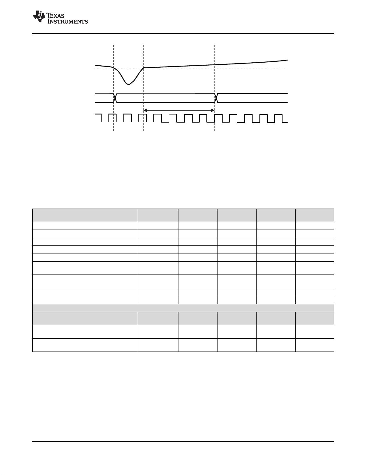
The device enters a brown-out condition whenever the input voltage dips below V
BROWN
(see Figure 4-1). This
condition must be considered during design of the power supply routing, especially if operating from a battery.
High-current operations (such as a TX packet) cause a dip in the supply voltage, potentially triggering a brown-
out. The resistance includes the internal resistance of the battery, contact resistance of the battery holder (4
contacts for a 2 x AA battery) and the wiring and PCB routing resistance.
8 Specifications Copyright © 2013–2014, Texas Instruments Incorporated
Submit Documentation Feedback
Product Folder Links: CC3100
剩余41页未读,继续阅读
2022-12-15 上传
2022-10-29 上传
2022-12-16 上传
2023-09-06 上传
2023-11-11 上传
2023-04-28 上传
2023-05-11 上传
2023-07-13 上传
2023-06-10 上传
2023-05-30 上传

不觉明了
- 粉丝: 4052
- 资源: 5759
 我的内容管理
展开
我的内容管理
展开


最新资源
- 平尾装配工作平台运输支撑系统设计与应用
- MAX-MIN Ant System:用MATLAB解决旅行商问题
- Flutter状态管理新秀:sealed_flutter_bloc包整合seal_unions
- Pong²开源游戏:双人对战图形化的经典竞技体验
- jQuery spriteAnimator插件:创建精灵动画的利器
- 广播媒体对象传输方法与设备的技术分析
- MATLAB HDF5数据提取工具:深层结构化数据处理
- 适用于arm64的Valgrind交叉编译包发布
- 基于canvas和Java后端的小程序“飞翔的小鸟”完整示例
- 全面升级STM32F7 Discovery LCD BSP驱动程序
- React Router v4 入门教程与示例代码解析
- 下载OpenCV各版本安装包,全面覆盖2.4至4.5
- 手写笔画分割技术的新突破:智能分割方法与装置
- 基于Koplowitz & Bruckstein算法的MATLAB周长估计方法
- Modbus4j-3.0.3版本免费下载指南
- PoqetPresenter:Sharp Zaurus上的开源OpenOffice演示查看器
