
Step 1. Chose the right MSPM0 MCU
The first step of migration is to choose the correct MSPM0 device for the application. To do this, the portfolio
section of this guide can be used to choose a MSPM0 family. To narrow down to a specific device using the
product selection tool. STM32G0 and MSPM0 share the M0+ core, but features such as memory size, power,
and key peripherals must also be considered. MSPM0 also offers many pin-to-pin scalable options, providing the
ability to easily scale to larger or smaller memory devices without changing anything else in the system.
For purposes of this example, we have chosen the MSPM0G3507 as the best fit for his application.
Step 2. Select hardware and order an EVM
Using an evaluation module (EVM) can expedite the migration process. For the MSPM0 MCUs, a LaunchPad
kit is the easiest hardware to begin on. LaunchPad kits are easy to use because they come with a built-in
programmer and are designed to enable rapid development.
The MSPM0G3507 has a LaunchPad development kit (LP-MSPM0G3507) that can be used for porting the
software.
Step 3. Setup software IDE and SDK
Before the software can be ported, a software development environment must be chosen and setup. Section
2.1 shows all of the IDEs supported by MSPM0. The migration and porting process is similar for any IDE that is
chosen. The latest version of the MSPM0 SDK should be used.
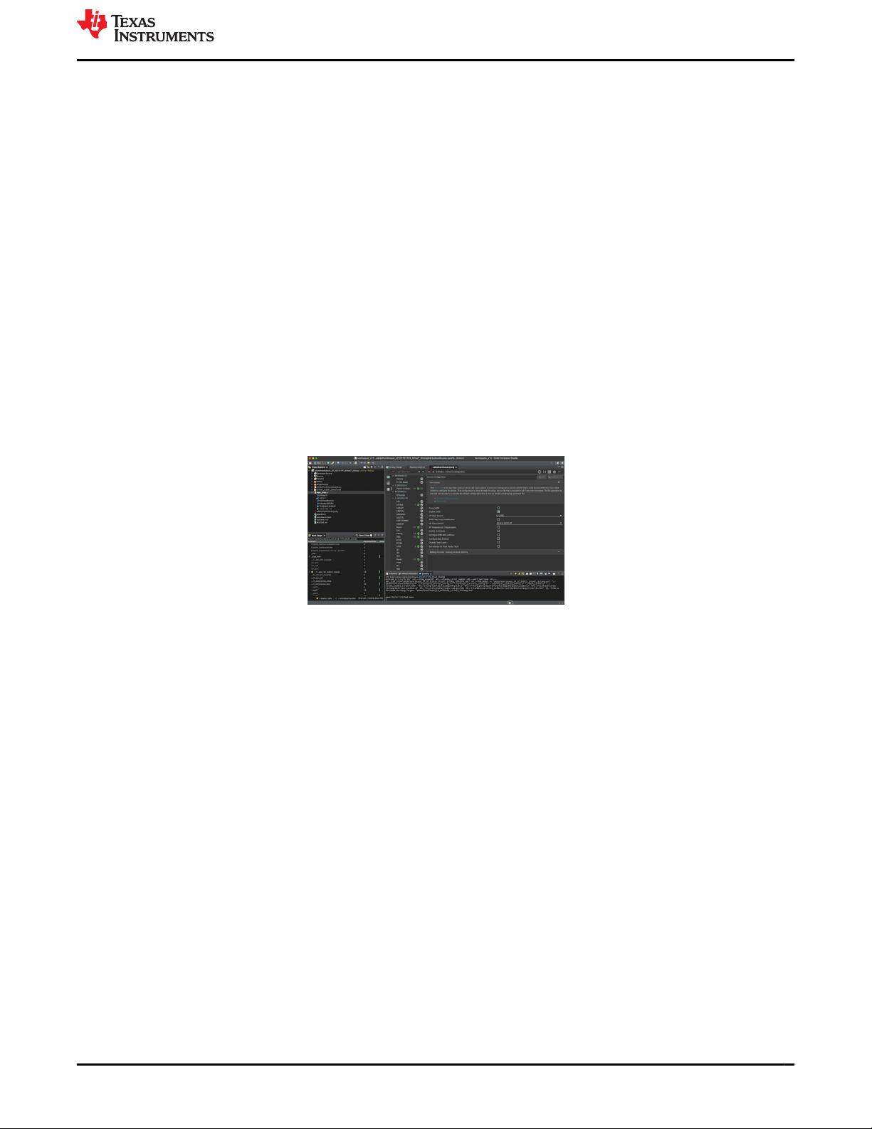
For this example, TI's CCS is the chosen IDE.
Figure 2-5. Code Composer Studio IDE
Step 4. Software porting
When the environment is ready, start using the MSPM0 SDK. As mentioned, the MSPM0 SDK is similar to the
STM32Cube software package. The MSPM0 SDK offers different layers for software development. MSPM0 TI
Drivers operate at a similar level to STM32Cube HAL, while MSPM0 DriverLib is comparable to the STM32Cube
low-level drivers. Most MSPM0 users find DriverLib level software is the best fit for their applications, so most
MSPM0 software examples are also DriverLib based. This example uses DriverLib.
One option when porting a project is to try to replace each section of code with equivalent MSPM0 DriverLib
APIs, but this is not generally the easiest path. Generally, it is best to first understand the application code being
ported. Then start with the closest MSPM0 example project and modify it to match the original code functionality.
This process is going to be shown below using a low-power UART example from STM32CubeG0. For more
complex projects using many peripherals, this process is typically repeated for each peripheral.
www.ti.com Ecosystem and Migration
SLAAE56A – NOVEMBER 2022 – REVISED MARCH 2023
Submit Document Feedback
Migration Guide From STM32
®
to Arm
®
-Based MSPM0 7
Copyright © 2023 Texas Instruments Incorporated

剩余35页未读,继续阅读

Build前沿
- 粉丝: 622
- 资源: 2146

下载权益

电子书特权

VIP文章

课程特权
开通VIP
 我的内容管理
收起
我的内容管理
收起
- 我的资源
快来上传第一个资源
 我的收益 登录查看自己的收益
 我的积分
登录查看自己的积分
我的积分
登录查看自己的积分
 我的C币
登录后查看C币余额
我的C币
登录后查看C币余额
 我的收藏
我的收藏  我的下载
我的下载  下载帮助
下载帮助

会员权益专享


最新资源
- VMP技术解析:Handle块优化与壳模板初始化
- C++ Primer 第四版更新:现代编程风格与标准库
- 计算机系统基础实验:缓冲区溢出攻击(Lab3)
- 中国结算网上业务平台:证券登记操作详解与常见问题
- FPGA驱动的五子棋博弈系统:加速与创新娱乐体验
- 多旋翼飞行器定点位置控制器设计实验
- 基于流量预测与潮汐效应的动态载频优化策略
- SQL练习:查询分析与高级操作
- 海底数据中心散热优化:从MATLAB到动态模拟
- 移动应用作业:MyDiaryBook - Google Material Design 日记APP
- Linux提权技术详解:从内核漏洞到Sudo配置错误
- 93分钟快速入门 LaTeX:从入门到实践
- 5G测试新挑战与罗德与施瓦茨解决方案
- EAS系统性能优化与故障诊断指南
- Java并发编程:JUC核心概念解析与应用
- 数据结构实验报告:基于不同存储结构的线性表和树实现
资源上传下载、课程学习等过程中有任何疑问或建议,欢迎提出宝贵意见哦~我们会及时处理!
点击此处反馈


