
AN625
16 Rev. 0.1
3.2.6. GPIO_PIN_CFG
Summary: Configures the GPIO pins
Command Stream
Reply Stream
Parameters:
GPIO0_PULL_CTL
0 = Disable pullup. Recommended setting if pin is driven.
1 = Enable pullup.
GPIO0_MODE[5:0]
0 = Do not modify the behavior of this pin.
1 = Input and output drivers disabled.
2 = CMOS output driven low.
3 = CMOS output driven high.
4 = CMOS input. This is used for all GPIO functions that require the pin to be an input (e.g., TX Direct Mode Data In).
The actual function of this pin is controlled by other properties.
5 = 32 kHz clock. Outputs 32 kHz clock selected using GLOBAL_CLK_CFG:CLK_32K_SEL. Output low if the
32 kHz clock is not enabled.
6 = BOOT_CLK. Outputs boot clock. This will only output when the device is in SPI ACTIVE state because that is the
only time the boot clock is active.
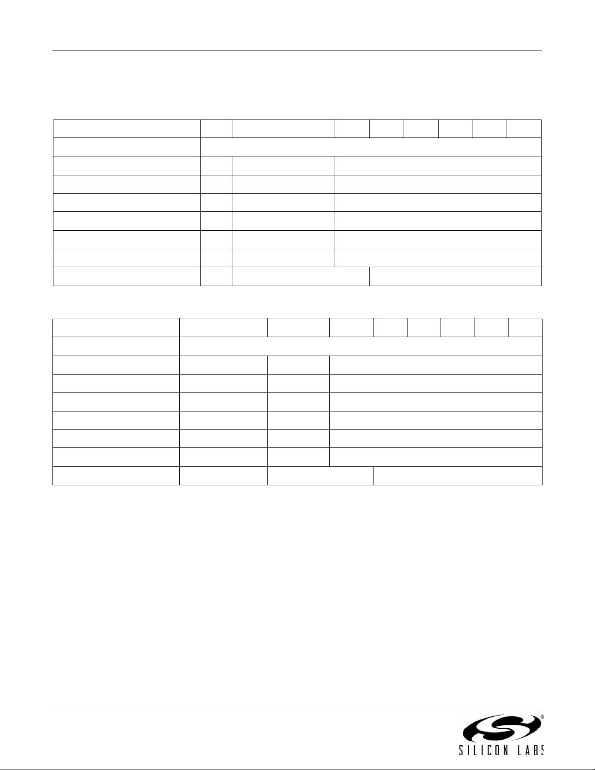
GPIO_PIN_CFG Command7 6 543210
CMD 0x13
GPIO0 0 GPIO0_PULL_CTL GPIO0_MODE[5:0]
GPIO1 0 GPIO1_PULL_CTL GPIO1_MODE[5:0]
GPIO2 0 GPIO2_PULL_CTL GPIO2_MODE[5:0]
GPIO3 0 GPIO3_PULL_CTL GPIO3_MODE[5:0]
NIRQ 0 NIRQ_DRV_PULL NIRQ_MODE[5:0]
SDO 0 SDO_PULL_CTL SDO_MODE[5:0]
GEN_CONFIG 0 DRV_STRENGTH[1:0] 00000
GPIO_PIN_CFG Reply 7 6 5 43210
CTS CTS[7:0]
GPIO0 GPIO0_STATE X GPIO0r_[5:0]
GPIO1 GPIO1_STATE X GPIO1r_[5:0]
GPIO2 GPIO2_STATE X GPIO2r_[5:0]
GPIO3 GPIO3_STATE X GPIO3r_[5:0]
NIRQ NIRQSTATE X NIRQr_[5:0]
SDO SDOSTATE X SDOr_[5:0]
GEN_CONFIG X DRV_STRENGTH[1:0] XXXXX


剩余115页未读,继续阅读

大音智库
- 粉丝: 3
- 资源: 22
 我的内容管理
展开
我的内容管理
展开


最新资源
- OptiX传输试题与SDH基础知识
- C++Builder函数详解与应用
- Linux shell (bash) 文件与字符串比较运算符详解
- Adam Gawne-Cain解读英文版WKT格式与常见投影标准
- dos命令详解:基础操作与网络测试必备
- Windows 蓝屏代码解析与处理指南
- PSoC CY8C24533在电动自行车控制器设计中的应用
- PHP整合FCKeditor网页编辑器教程
- Java Swing计算器源码示例:初学者入门教程
- Eclipse平台上的可视化开发:使用VEP与SWT
- 软件工程CASE工具实践指南
- AIX LVM详解:网络存储架构与管理
- 递归算法解析:文件系统、XML与树图
- 使用Struts2与MySQL构建Web登录验证教程
- PHP5 CLI模式:用PHP编写Shell脚本教程
- MyBatis与Spring完美整合:1.0.0-RC3详解
资源上传下载、课程学习等过程中有任何疑问或建议,欢迎提出宝贵意见哦~我们会及时处理!
点击此处反馈


