
1 Basic Buck Topology
++
Vin
Vout
Feedback
Network
Lout
Cout
Catch
Diode
BootCapacitor
Cin
FET
Switch
REF
Error Amp
PWMControl
&GateDrive
IntegratedFunctions
Application Report
SLVA257A – January 2007 – Revised August 2007
Using the TPS5430 as an Inverting Buck-Boost Converter
John Tucker ........................................................................................................ PMP Systems Power
ABSTRACT
The wide input voltage range SWIFT™ (Switcher With Integrated FET) dc/dc
converters are typically used as step-down converters where the derived output is a
positive voltage less than the input voltage source. In some cases, it may be required
to generate a negative voltage from the input voltage source. In such instances, it is
possible to configure the TPS5430/20/10 devices in an inverting buck–boost topology,
where the output voltage is negative with respect to ground.
Contents
1 Basic Buck Topology ............................................................................... 1
2 Inverting Buck-Boost Topology ................................................................... 2
3 Design Considerations ............................................................................. 2
4 Circuit Performance ................................................................................ 4
5 Conclusion ........................................................................................... 7
List of Figures
1 Buck Topology ...................................................................................... 1
2 Inverting Buck-Boost Topology ................................................................... 2
3 TPS5430 Buck–Boost Application ................................................................ 3
4 Closed Loop Response ............................................................................ 4
5 Transient Response ................................................................................ 5
6 Output Voltage Ripple and PH Node Voltage .................................................. 5
7 Efficiency ............................................................................................. 6
8 Load Regulation .................................................................................... 6
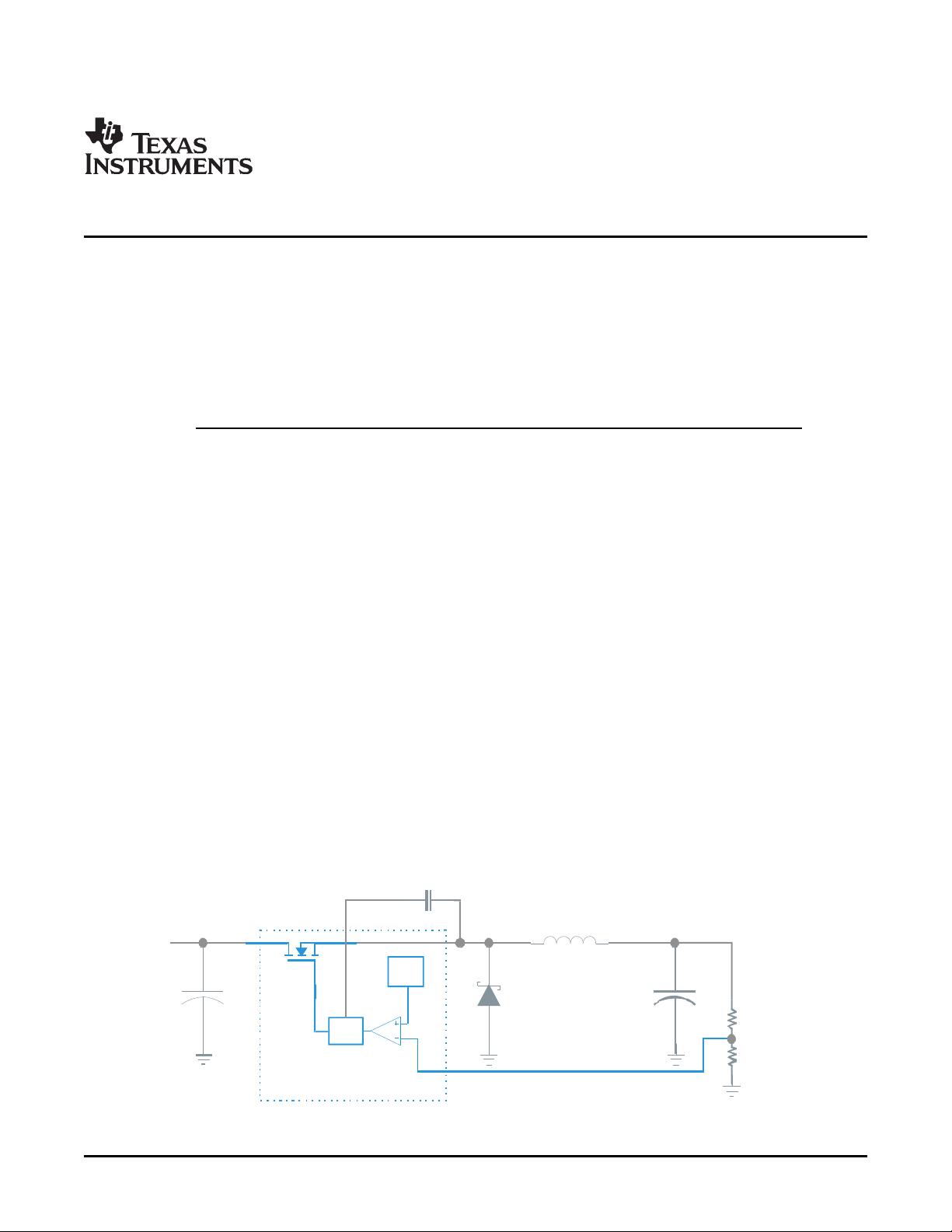
To understand the circuit operation, consider the basic topology of the buck converter as shown in
Figure 1 .
Figure 1. Buck Topology
SWIFT, PowerPAD are trademarks of Texas Instruments.
SLVA257A – January 2007 – Revised August 2007 Using the TPS5430 as an Inverting Buck-Boost Converter 1
Submit Documentation Feedback

hpfei77
- 粉丝: 5
- 资源: 3
 我的内容管理
收起
我的内容管理
收起
- 我的资源
快来上传第一个资源
 我的收益 登录查看自己的收益
 我的积分
登录查看自己的积分
我的积分
登录查看自己的积分
 我的C币
登录后查看C币余额
我的C币
登录后查看C币余额
 我的收藏
我的收藏  我的下载
我的下载  下载帮助
下载帮助

会员权益专享


最新资源
- 数据结构1800题含完整答案详解.doc
- 医疗企业薪酬系统设计与管理方案.pptx
- 界面与表面技术界面理论与表面技术要点PPT学习教案.pptx
- Java集合排序及java集合类详解(Collection、List、Map、Set)讲解.pdf
- 网页浏览器的开发 (2).pdf
- 路由器原理与设计讲稿6-交换网络.pptx
- 火电厂锅炉过热汽温控制系统设计.doc
- 企业识别CIS系统手册[收集].pdf
- 物业管理基础知识.pptx
- 第4章财务预测.pptx
- 《集成电路工艺设计及器件特性分析》——实验教学计算机仿真系.pptx
- 局域网内共享文件提示没有访问权限的问题借鉴.pdf
- 第5章网络营销策略.pptx
- 固井质量测井原理PPT教案.pptx
- 毕业实习总结6篇.doc
- UGNX建模基础篇草图模块PPT学习教案.pptx
资源上传下载、课程学习等过程中有任何疑问或建议,欢迎提出宝贵意见哦~我们会及时处理!
点击此处反馈


评论9