没有合适的资源?快使用搜索试试~ 我知道了~
首页MAX9288COAXEVKIT-MAX9290COAXEVKIT.pdf
MAX9288COAXEVKIT-MAX9290COAXEVKIT.pdf
需积分: 50 338 浏览量
更新于2023-03-03
评论
收藏 5.85MB PDF 举报
The MAX9288/MAX9290 evaluation kit (EV kit) provides a proven design to evaluate the MAX9288 and MAX9290 high-bandwidth gigabit multimedia serial link (GMSL) deserializers with spread spectrum and full-duplex control channel, with the use of a standard FAKRA coaxial cable. The EV kit also includes Windows Vista®-, and Windows® 7-compatible software that provides a simple graphical user interface (GUI) for exercising features of the device. The EV kit comes with a MAX9288 or MAX9290 IC installed.
资源详情
资源评论
资源推荐

Evaluates: MAX9288/MAX9290
MAX9288/MAX9290 Evaluation Kit
General Description
The MAX9288/MAX9290 evaluation kit (EV kit) provides
a proven design to evaluate the MAX9288 and MAX9290
high-bandwidth gigabit multimedia serial link (GMSL)
deserializers with spread spectrum and full-duplex control
channel, with the use of a standard FAKRA coaxial cable.
The EV kit also includes Windows Vista
®
-, and Windows
®
7-compatible software that provides a simple graphical
user interface (GUI) for exercising features of the device.
The EV kit comes with a MAX9288 or MAX9290 IC
installed.
For complete GMSL evaluation, using a standard FAKRA
coaxial cable, order the MAX9288/MAX9290 coax EV kit
and a companion serializer board (e.g., the MAX9275/
MAX9279 coax EV kit referenced in this document). For
testing with STP cable, also order the MAXCOAX2STP-
HSD adapter kit. Only one adapter kit is needed per pair
of serializer and deserializer boards.
Note: In the following sections, the term serializer refers to
the MAX9275 or MAX9279 ICs and the term deserializer
refers to the MAX9288 or MAX9290 ICs. The term SerDes
refers to serializer(s) and deserializer(s).
This document applies to both coax and STP EV kits. This
document covers coax cables, but the information applies
equally to STP cables.
319-100319; Rev 0; 2/19
Ordering Information appears at end of data sheet.
Windows and Windows Vista are registered trademarks and
registered service marks of Microsoft Corporation.
Features
● Drives 4-Channel CSI-2 Output
● Windows Vista- and Windows 7-Compatible Software
● USB-Controlled Interface (Cable Included)
● USB Powered
● Proven PCB Layout
● Fully Assembled and Tested
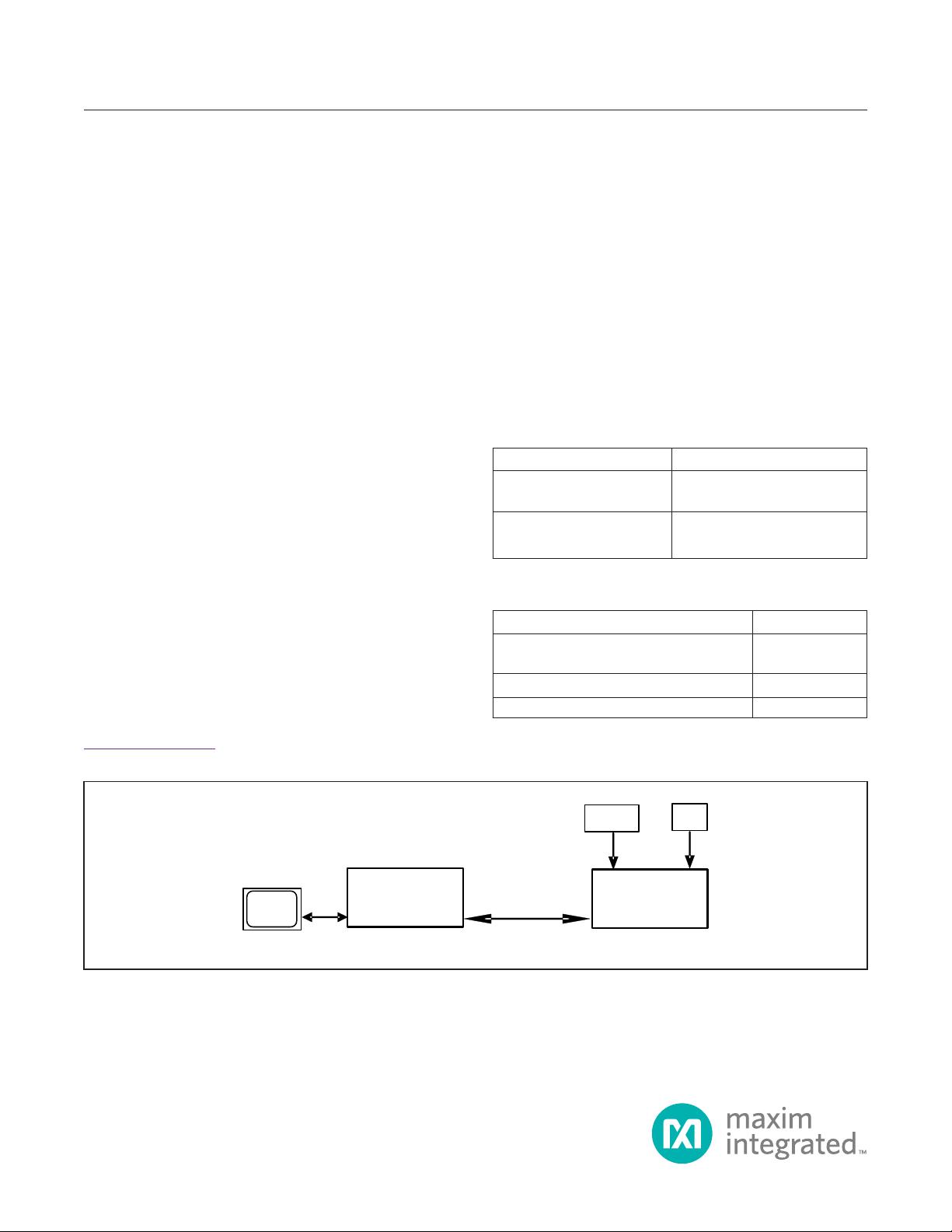
COMPUTER
USB
(USB Powered)
IN+
POWER
SUPPLY
+5V
OUT0+
PCLK
FUNCTION
GENERATOR
DESERIALIZER
SERIALIZER
2m COAX CABLE
Figure 1. MAX9288/MAX9290 Evaluation Board Test Setup
DESCRIPTION DESCRIPTION
MAXSerDesEV-N_Vxxxx_
Install.EXE
Installs the EV kit les in your
computer
MAXSerDesEV-N.EXE
Graphical user interface (GUI)
program
DESCRIPTION QTY
MAX9288 coax EV kit board or MAX9290
coax EV kit board
1
2m FAKRA coax cable assembly 1
USB cable
1
MAX9288/MAX9290 EV Kit Files
Items Included in the EV Kit Package

Maxim Integrated
│
2
www.maximintegrated.com
Evaluates: MAX9288/MAX9290
MAX9288/MAX9290 Evaluation Kit
Quick Start
This procedure applies to both coax and STP evaluation
kits. The coax evaluation kit is referenced here.
Required Equipment
● MAX9288/MAX9290 deserializer coax EV kit
● MAX9275/MAX9279 serializer coax EV kit
● 2m FAKRA cable assembly (included in the
MAX9288/MAX9290 coax EV kit)
● > 20MHz function generator
● Windows Vista or Windows 7 PC with a spare USB
port (direct 500mA connection required; do not use a
bus-powered hub)
● 5V DC, 500mA power supply
Note: In the following sections, software-related items are
identied by bolding. Text in bold refers to items directly
from the EV kit software. Text in bold and underlined
refers to items from the Windows operating system.
Procedure
The EV kit is fully assembled and tested. Follow the steps
below to verify board operation:
1) Download and install the latest version of the EV kit
software from www.maximintegrated.com.
a. Search for the MAX9288.
b. Select MAX9288 | Design Resources |
Software | MAXSerDes-N and download the
MAXSerDes-Nxxxx_Install.zip file.
c. Open the downloaded zip le and run
MAXSerDes-Nxxxx_Install.exe.
d. The installation application downloads and installs
the USB driver for the Nuvoton microcontroller. If the
USB driver installation is not successful, install the
appropriate USB driver for your computer, available at
http://www.ftdichip.com/Drivers/VCP.htm.
2) Verify that jumpers on the deserializer board are in
their default positions, as shown in Figure 12.
3) Verify that jumpers on the serializer board are in their
default positions, as shown in Figure 13.
4) Set up the system, as shown in Figure 1.
5) Power up the serializer board by connecting the
power supply to the +5VIN/GND terminals on the
serializer board.
6) Power up the deserializer board by connecting the
USB cable between the PC's USB port and
connector J10 on the deserializer board.
7) Connect the FAKRA cable from the OUT+ terminal
on the serializer board to the IN+ terminal on the
deserializer board.
8) Connect the pixel clock and function generator to the
serializer EV kit board header's H1 PCLK_IN pin.
9) Turn on the power supply and function generator.
10) Verify that LED_PWR on the serializer EV kit board
lights up, indicating that the board is powered.
11) Verify that the LOCK LED on the deserializer EV kit
board illuminates, indicating that the link has been
successfully established. If the LOCK LED is off or the
ERR LED is on, consult the Troubleshooting section
and x the problem before continuing.
12) Start the EV kit software by selecting Start | Pro-
grams | Maxim Integrated | MAXSerDesEV-N |
MAXSerDesEV-N
13) In case an operating evaluation board with a
Nuvoton microcontroller is not found, a window opens,
warning as such (Figure 2). Press OK to continue and
start the GUI anyway or press Cancel to terminate the
application. Consult the Troubleshooting section and
x the problem before continuing.
14) When an operating Nuvoton microcontroller is found,
the GUI checks the rmware version in the microcon-
troller and prompts the user to update. Press OK to
continue working, or press Cancel to stop the applica-
tions (Figure 3).
Figure 3. MAXSerDesEV-N EV Kit Software: Warning!
(Microcontroller Firmware is Not the Latest Version)
Figure 2. MAXSerDesEV-N EV Kit Software: Warning!
(Nuovoton Microcontroller is Not Detected!)

Maxim Integrated
│
3
www.maximintegrated.com
Evaluates: MAX9288/MAX9290
MAX9288/MAX9290 Evaluation Kit
15) The Conguration Settings window appears, as
shown in Figure 4. The GUI automatically scans all
possible slave addresses and identies the
connected devices (DUTs) based on the Device IDs
read from the DUTs’ internal registers.
16) Once the Conguration Settings window is open,
press the Identify Devices button to search for
connected devices. Once the devices are identi-
ed, the corresponding conguration jumpers are
displayed to help users congure the serializer and
deserializer. Only Link Type and Device Address
selections on Conguration Setting window affect
the EV kit operation. Other items are for user refer-
ence only.
17) Press the Connect button to open the Evaluation
Kit window and the DUTs’ register maps (Figure 5).
The GUI reads all the SerDes’ internal registers and
updates the corresponding tabs.
18) Press the Read All MAX9279 button in the Serializer
group box to read all serializer registers.
19) Press the Deserializer tab and then press Read All
MAX9290 in the Deserializer group box to read all
deserializer registers.
20) Select any of the other tabs to evaluate other
functions of the SerDes.
Detailed Description of Software
To start the MAX9288/MAX9290 EV kit GUI, select Start
| Programs | Maxim Integrated | MAXSerDesEV-N |
MAXSerDesEV-N.
Conguration Settings Window
The Conguration Settings window is the rst window
that opens after successful program launch. It allows the
user to specify serializer and deserializer board setup and
mode of operation (Figure 4).
Controller Group Box
From the Controller group box, select Coax or STP
from the Link Type drop-down list, I2C or UART from
the Bus drop-down list, and click on either the Serializer
or Deserializer radio button to determine which device
should connect to the USB controller. Upon changing any
of these parameters, the selection in the jumper listing
highlights automatically, prompting the user to manually
make the corresponding jumper-position changes on the
EV kit boards.
Figure 4. MAXSerDesEV-N EV Kit Software: Configuration Settings Window (Shown with MAX9279, MAX9290 EV Kits Connected)

Maxim Integrated
│
4
www.maximintegrated.com
Evaluates: MAX9288/MAX9290
MAX9288/MAX9290 Evaluation Kit
Serializer Jumper Selection Block
The Serializer Jumper Selection block lists the jumpers
on the evaluation board of the selected Device ID and
shows the correct shunt positions based on the conditions
selected in the Controller block.
Deserializer Jumper Selection Block
The Deserializer Jumper Selection block lists the jump-
ers on the evaluation board of the selected Device ID and
shows the correct shunt positions based on the conditions
selected in the Controller block.
Figure 12 shows jumper setting on the MAX9288/
MAX9290 PCB for coax cable and I
2
C communication
with a USB cable connected to the deserializer board.
Refer to the MAX9288/MAX9290 IC data sheet for
detailed conguration information. See Table 1 for the
deserializer jumper settings and descriptions.
Identify Devices Button
The Identify Devices button causes the GUI to scan
the system and search for slave addresses on the bus.
Upon successful communication, it reads the Device ID
register from the DUT(s) and displays the correspond-
ing jumper lists on the Serializer Jumper Selection
and Deserializer Jumper Selection blocks. It is also
possible to manually select a device from the Device ID
drop-down list and manually change slave address in the
Device Address edit box. It is a good practice to utilize
the Identify Devices button and verify communication
with the DUTs before attempting to Connect.
To enable the control channel and communicate with the
serializer without applying PCLK, select Enable CLINK
Identify and then press the Connect button.
The following sections provide a brief overview of the
function buttons on the Conguration Settings window.
Connect Button
The Connect button opens up the Evaluation Kit
window. The GUI reads the SerDes registers and updates
on-screen register maps for both. Successful communica-
tion is indicated by green LED indicators. The LED indica-
tor's color glow red in case of a communication problem.
Cancel - Do No Connect Button
The Cancel - Do Not Connect button opens the
Evaluation Kit window without attempting to connect
to the microcontroller. Although there is no communi-
cation with the microcontroller, all functions and tabs
corresponding to the selected Device IDs on the
Evaluation Kit window become active once there.
JUMPER* SIGNAL
DEFAULT
POSITION
FUNCTION
AVDD18 (JU30) AVDD 1.8V
INT* AVDD 1.8V supplied internally
EXT AVDD 1.8V supplied through the AVDD18 terminal
AVDD33 (JU32) AVDD 3.3V
INT* AVDD 3.3V supplied internally
EXT AVDD 3.3V supplied through the AVDD33 terminal
DVDD18 (JU31) JU_DVDD
INT* DVDD 1.8V supplied internally
EXT DVDD 1.8V supplied through the DVDD18 terminal
IOVDD (JU33) IOVDD
3.3V* IOVDD supplied internally
2.5V IOVDD supplied internally
1.8V IOVDD supplied internally
EXT IOVDD supplied through the IOVDD terminal
J6 IOVDD Short* Measure current drawn by U1 through the IOVDD pin
J6 JU_VDDIO
Short* VDDIO applied to U1
Open Connect amp meter to measure current drawn by U1 through the IOVDD pin
JU3
PCB main
power
USB* 5V supplied from the USB port
REG
5V supplied from the external supply applied on the +5V terminal
+5VN
Not an option in the rev P2 PCB. Warning: Power applied on the +5VIN ter-
minals is directly applied to the board circuitry ghting with selection on JU3.
Table 1. Deserializer Jumper Settings and Descriptions

Maxim Integrated
│
5
www.maximintegrated.com
Evaluates: MAX9288/MAX9290
MAX9288/MAX9290 Evaluation Kit
Table 1. Jumper Settings/Descriptions (continued)
JUMPER* SIGNAL
DEFAULT
POSITION
FUNCTION
BWS
JU_BWS
L* PCLKIN > 12.5MHz, 32-bit mode
H PCLKIN > 12.5MHz, 32-bit mode
Open PCLKIN > 33.33MHz 27-bit high bandwidth
I2CSEL (JU18) I2CSEL
L* UART-to-UART or UART-to-I
2
C mode
H I
2
C-to-I
2
C mode
GPI (JU24) GPI
L* GPI pin pulled low
H GPI pin pulled high
CX_TP (JU34) CXTP
L STP Link (Table 5)
H* Coax+ Link (Table 5)
CDS CDS
L* µC is connected at the serializer side
H µC is connected at the deserializer
HIM HIM
L* Reveres channel in legacy mode
H Reveres channel in high immunity mode
MS MS
L* Base mode
H Bypass mode
PWDN PWDN
H* Deserializer is powered on
L Deserializer is powered off
HS_RX RX/SDA
RX* UART-to-UART or UART-to-I
2
C mode
SDA I
2
C-to-I
2
C mode
HS_RX RX/SDA
RX* UART-to-UART or UART-to-I
2
C mode
SDA I
2
C-to-I
2
C mode
GPIO0 (JU16) GPIO0
L GPIO0 pin is forced low
H GPIO0 pin is forced high
Open* U1 drives GPIO0 pin
GPIO1 (JU17) GPIO1
L
GPIO1 pin is forced low
H GPIO1 pin is forced high
Open* U1 drives GPIO1 pin
ADD0 (JU19) ADD0/CNTL0
L* See Table 5
H See Table 5
ADD1 (JU20) ADD1/CNTL3
L* See Table 5
H See Table 5
ADD2 (JU23) ADD2/CNTL2
L* See Table 5
H See Table 5
J11 VDD_REF
Short* U8 and U37 level shifters supply is from internal 3.3V.
Open U8 and U37 level shifters supply is applied externally through J12-1.
J12
External µC
connection
—
Apply external µC RX/SDA, TX/SCL, GND to pins as marked. The logic level
can be selected from internal 3.3V (J11) or applied externally on pin 1.
剩余28页未读,继续阅读


安全验证
文档复制为VIP权益,开通VIP直接复制

评论0