没有合适的资源?快使用搜索试试~ 我知道了~
首页STM8的编程调试接口SWIM
资源详情
资源评论
资源推荐
January 2008 Rev 1 1/37
UM0470
User manual
STM8 SWIM communication protocol and debug module
Introduction
This manual has been written for developers who need to build programming, testing or
debugging tools for the STM8 microcontroller family. It explains the debug architecture of the
STM8 core.
The STM8 debug system consists of 2 modules.
DM - Debug module
SWIM - Single wire interface module
Related documentation
● STM8 Flash programming reference manual (PM0047)
www.st.com
Contents UM0470
2/37
Contents
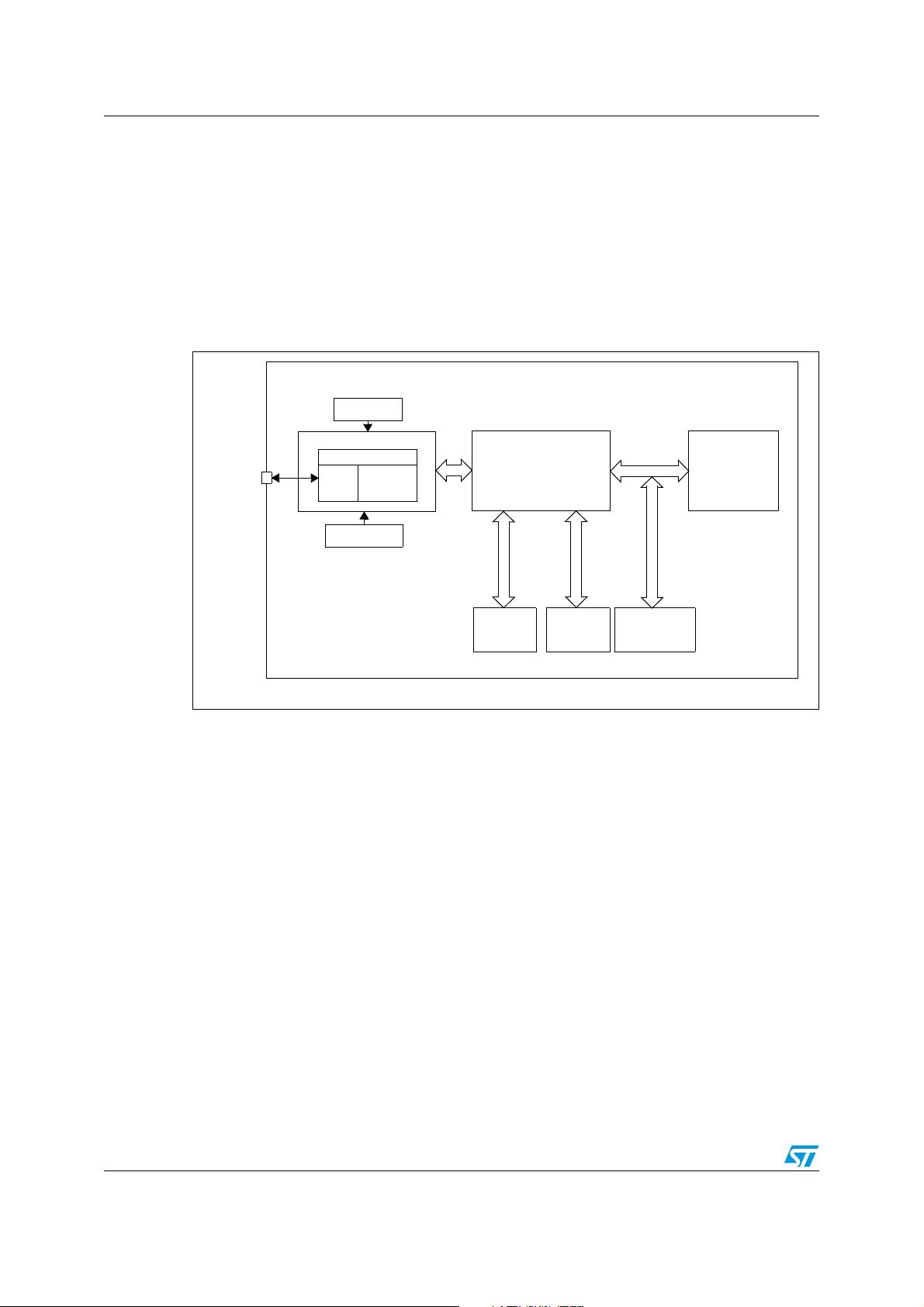
1 Debug system overview . . . . . . . . . . . . . . . . . . . . . . . . . . . . . . . . . . . . . . 4
2 Communication layer . . . . . . . . . . . . . . . . . . . . . . . . . . . . . . . . . . . . . . . . 5
3 Single wire interface module (SWIM) . . . . . . . . . . . . . . . . . . . . . . . . . . . 6
3.1 Operating modes . . . . . . . . . . . . . . . . . . . . . . . . . . . . . . . . . . . . . . . . . . . . 6
3.2 SWIM entry sequence . . . . . . . . . . . . . . . . . . . . . . . . . . . . . . . . . . . . . . . . 7
3.3 Bit format . . . . . . . . . . . . . . . . . . . . . . . . . . . . . . . . . . . . . . . . . . . . . . . . . . 8
3.3.1 High speed bit format . . . . . . . . . . . . . . . . . . . . . . . . . . . . . . . . . . . . . . . . 9
3.3.2 Low speed bit format . . . . . . . . . . . . . . . . . . . . . . . . . . . . . . . . . . . . . . . . 9
3.4 SWIM communication protocol . . . . . . . . . . . . . . . . . . . . . . . . . . . . . . . . . 10
3.5 SWIM commands . . . . . . . . . . . . . . . . . . . . . . . . . . . . . . . . . . . . . . . . . . . 11
3.5.1 SRST: system reset . . . . . . . . . . . . . . . . . . . . . . . . . . . . . . . . . . . . . . . . 11
3.5.2 ROTF: read on the fly . . . . . . . . . . . . . . . . . . . . . . . . . . . . . . . . . . . . . . 11
3.5.3 WOTF: write on the fly . . . . . . . . . . . . . . . . . . . . . . . . . . . . . . . . . . . . . . 11
3.6 SWIM communication reset . . . . . . . . . . . . . . . . . . . . . . . . . . . . . . . . . . . 12
3.7 CPU register access . . . . . . . . . . . . . . . . . . . . . . . . . . . . . . . . . . . . . . . . . 12
3.8 SWIM communication in Halt mode . . . . . . . . . . . . . . . . . . . . . . . . . . . . . 13
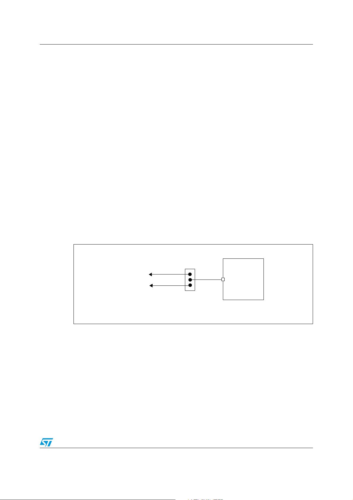
3.9 Physical layer . . . . . . . . . . . . . . . . . . . . . . . . . . . . . . . . . . . . . . . . . . . . . . 14
3.10 STM8 SWIM registers . . . . . . . . . . . . . . . . . . . . . . . . . . . . . . . . . . . . . . . 15
3.10.1 SWIM control status register (SWIM_CSR) . . . . . . . . . . . . . . . . . . . . . . 15
3.10.2 SWIM clock control register (CLK_SWIMCCR) . . . . . . . . . . . . . . . . . . . 17
4 Debug module (DM) . . . . . . . . . . . . . . . . . . . . . . . . . . . . . . . . . . . . . . . . 18
4.1 Introduction . . . . . . . . . . . . . . . . . . . . . . . . . . . . . . . . . . . . . . . . . . . . . . . 18
4.2 Main features . . . . . . . . . . . . . . . . . . . . . . . . . . . . . . . . . . . . . . . . . . . . . . 18
4.3 Debug . . . . . . . . . . . . . . . . . . . . . . . . . . . . . . . . . . . . . . . . . . . . . . . . . . . . 19
4.3.1 Reset . . . . . . . . . . . . . . . . . . . . . . . . . . . . . . . . . . . . . . . . . . . . . . . . . . . 19
4.3.2 Breakpoints . . . . . . . . . . . . . . . . . . . . . . . . . . . . . . . . . . . . . . . . . . . . . . 19
4.3.3 Abort . . . . . . . . . . . . . . . . . . . . . . . . . . . . . . . . . . . . . . . . . . . . . . . . . . . 20
4.3.4 Watchdog control . . . . . . . . . . . . . . . . . . . . . . . . . . . . . . . . . . . . . . . . . . 20
4.3.5 Interaction with SWIM . . . . . . . . . . . . . . . . . . . . . . . . . . . . . . . . . . . . . . 20
4.4 Breakpoint decoding table . . . . . . . . . . . . . . . . . . . . . . . . . . . . . . . . . . . . 20
UM0470 Contents
3/37
4.5 Software breakpoint mode . . . . . . . . . . . . . . . . . . . . . . . . . . . . . . . . . . . . 22
4.6 Timing description . . . . . . . . . . . . . . . . . . . . . . . . . . . . . . . . . . . . . . . . . . 23
4.7 Abort . . . . . . . . . . . . . . . . . . . . . . . . . . . . . . . . . . . . . . . . . . . . . . . . . . . . . 23
4.8 Data breakpoint . . . . . . . . . . . . . . . . . . . . . . . . . . . . . . . . . . . . . . . . . . . . 23
4.9 Instruction breakpoint . . . . . . . . . . . . . . . . . . . . . . . . . . . . . . . . . . . . . . . . 24
4.10 Step mode . . . . . . . . . . . . . . . . . . . . . . . . . . . . . . . . . . . . . . . . . . . . . . . . 25
4.11 Application notes . . . . . . . . . . . . . . . . . . . . . . . . . . . . . . . . . . . . . . . . . . . 26
4.11.1 Illegal Memory access . . . . . . . . . . . . . . . . . . . . . . . . . . . . . . . . . . . . . . 26
4.11.2 Forbidden stack access . . . . . . . . . . . . . . . . . . . . . . . . . . . . . . . . . . . . . 26
4.11.3 DM break . . . . . . . . . . . . . . . . . . . . . . . . . . . . . . . . . . . . . . . . . . . . . . . . 26
4.12 DM registers . . . . . . . . . . . . . . . . . . . . . . . . . . . . . . . . . . . . . . . . . . . . . . . 27
4.12.1 DM breakpoint register 1 extended byte (DM_BKR1E) . . . . . . . . . . . . . 28
4.12.2 DM breakpoint register 1 high byte (DM_BKR1H) . . . . . . . . . . . . . . . . . 28
4.12.3 DM breakpoint register 1 low byte (DM_BKR1L) . . . . . . . . . . . . . . . . . . 28
4.12.4 DM breakpoint register 2 extended byte (DM_BKR2E) . . . . . . . . . . . . . 29
4.12.5 DM breakpoint register 2 high byte (DM_BKR2H) . . . . . . . . . . . . . . . . . 29
4.12.6 DM breakpoint register 2 low byte (DM_BKR2L) . . . . . . . . . . . . . . . . . . 29
4.12.7 DM control register 1 (DM_CR1) . . . . . . . . . . . . . . . . . . . . . . . . . . . . . . 30
4.12.8 DM control register 2 (DM_CR2) . . . . . . . . . . . . . . . . . . . . . . . . . . . . . . 31
4.12.9 DM control/status register 1 (DM_CSR1) . . . . . . . . . . . . . . . . . . . . . . . 32
4.12.10 DM control/status register 2 (DM_CSR2) . . . . . . . . . . . . . . . . . . . . . . . 33
4.12.11 DM enable function register (DM_ENFCTR) . . . . . . . . . . . . . . . . . . . . . 34
4.12.12 Summary of SWIM, DM and core register maps . . . . . . . . . . . . . . . . . . 35
5 Revision history . . . . . . . . . . . . . . . . . . . . . . . . . . . . . . . . . . . . . . . . . . . 36
Debug system overview UM0470
4/37
1 Debug system overview
The STM8 debug system interface allows a debugging or programming tool to be connected
to the MCU through a single wire bidirectional communication based on open-drain line.
It provides non-intrusive read/write access to RAM and peripherals during program
execution
The block diagram is shown in Figure 1.
Figure 1. Debug system block diagram
The debug module uses the two internal clock sources present in the device, the LSI Low
Speed Internal clock (usually in the range 30 kHz-200 kHz, depending on the product) one
and the HSI High Speed Internal clock (usually in the range 10 MHz to 25 MHz, depending
on the device). The clocks are automatically started when necessary.
SWIM Entry
LSI oscillator
HSI oscillator
Comm
Layer
Command
Decode
Debug module (DM)
STM8
Core
Peripherals
SWIM pin
Peripheral Bus
CPU Bus
SWIM module
RAM
Flash/
RAM Bus
STM8
Data EEPROM
UM0470 Communication layer
5/37
2 Communication layer
The SWIM module is a single wire interface based on asynchronous, high sink (8 mA),
open-drain, bidirectional communication.
While the CPU is running, the SWIM module allows non-intrusive read/write accesses to be
performed on-the-fly to the RAM and peripheral registers, for debug purposes.
In addition, while the CPU is stalled, the SWIM module allows read/write accesses to be
performed to any other part of the MCU’s memory space (Data EEPROM and program
memory).
CPU registers (A, X, Y, CC, SP) can also be accessed. These registers are mapped in
memory and can be accessed in the same way as other memory addresses.
● Register, peripherals and memory can be accessed only when the SWIM_DM bit is set.
● When the system is in HALT, WFI or readout protection mode, the NO_ACCESS flag in
the SWIM_CSR register is set. In this case, it is forbidden to perform any accesses
because parts of the device may not be clocked and a read access could return
garbage or a write access might not succeed.
The SWIM module can perform a MCU device software reset.
The SWIM pin can also be used by the MCU target application as a standard I/O port with
some restrictions if you also want to use it for debug. The safest way is to provide a strap
option on the application PCB.
Figure 2. SWIM pin external connections
STM8
Application I/O
SWIM interface for tools
Jumper selection for
debug purposes
SWIM pin
剩余36页未读,继续阅读
江南一书生
- 粉丝: 0
- 资源: 1
上传资源 快速赚钱
- 我的内容管理 收起
- 我的资源 快来上传第一个资源
- 我的收益 登录查看自己的收益
- 我的积分 登录查看自己的积分
- 我的C币 登录后查看C币余额
- 我的收藏
- 我的下载
- 下载帮助
会员权益专享
最新资源
- stc12c5a60s2 例程
- Android通过全局变量传递数据
- c++校园超市商品信息管理系统课程设计说明书(含源代码) (2).pdf
- 建筑供配电系统相关课件.pptx
- 企业管理规章制度及管理模式.doc
- vb打开摄像头.doc
- 云计算-可信计算中认证协议改进方案.pdf
- [详细完整版]单片机编程4.ppt
- c语言常用算法.pdf
- c++经典程序代码大全.pdf
- 单片机数字时钟资料.doc
- 11项目管理前沿1.0.pptx
- 基于ssm的“魅力”繁峙宣传网站的设计与实现论文.doc
- 智慧交通综合解决方案.pptx
- 建筑防潮设计-PowerPointPresentati.pptx
- SPC统计过程控制程序.pptx
资源上传下载、课程学习等过程中有任何疑问或建议,欢迎提出宝贵意见哦~我们会及时处理!
点击此处反馈
安全验证
文档复制为VIP权益,开通VIP直接复制
信息提交成功
评论7