没有合适的资源?快使用搜索试试~ 我知道了~
首页ansysworkbench电磁场仿真完整例子.pdf
ansysworkbench电磁场仿真完整例子.pdf
2星 需积分: 37 90 下载量 34 浏览量
更新于2023-03-16
评论 7
收藏 3.46MB PDF 举报
ansys workbench电磁场仿真完整例子,详细介绍了如何用ANSYS workbench做静态电磁仿真,动态电磁仿真。
资源详情
资源评论
资源推荐
Workbench Simulation of a Magnetic Valve
October 10, 2006
A Guide for Magnetic Simulation of a Magnetic Valve
ANSYS Workbench Simulation
Page 1 of 23
Introduction
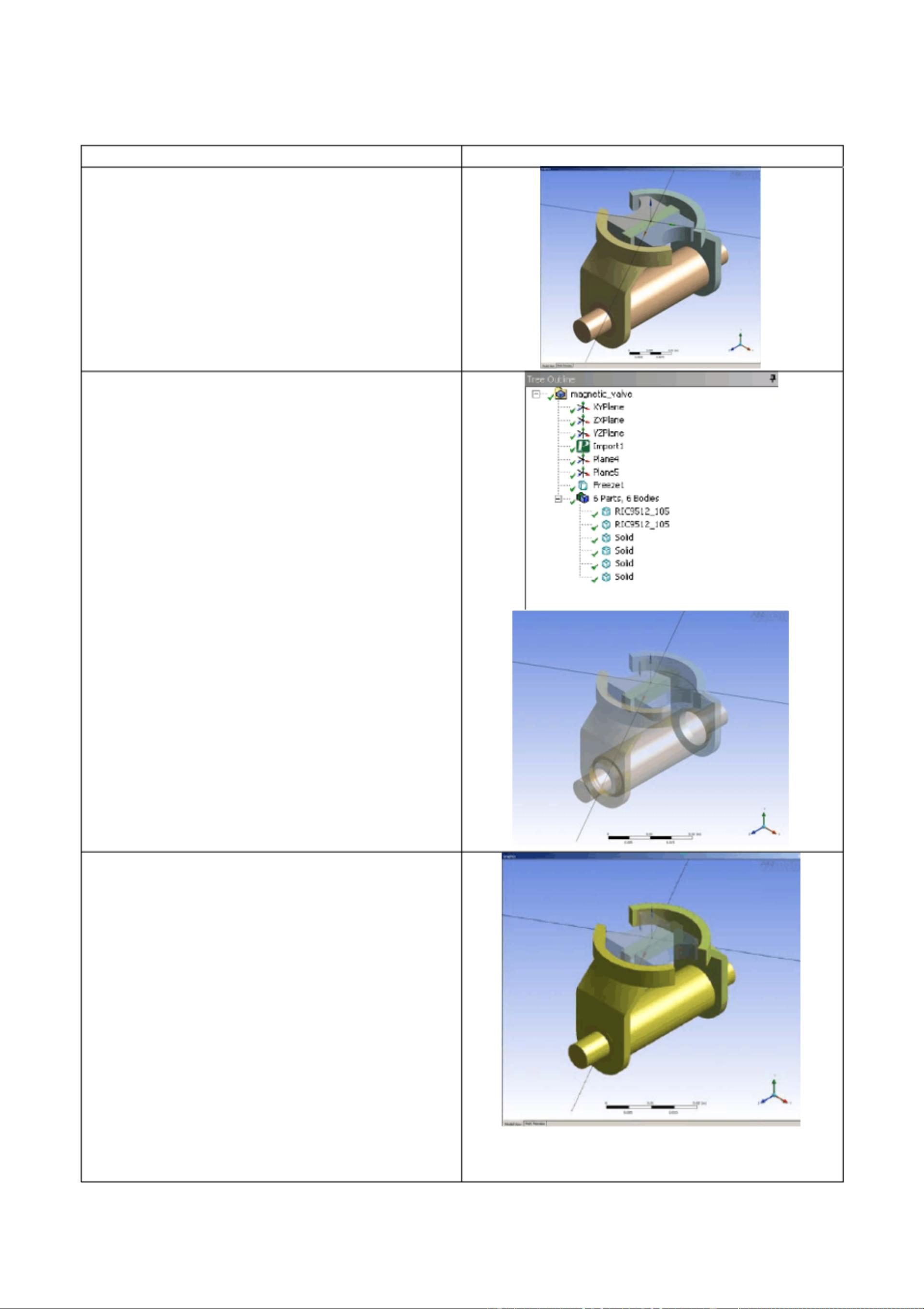
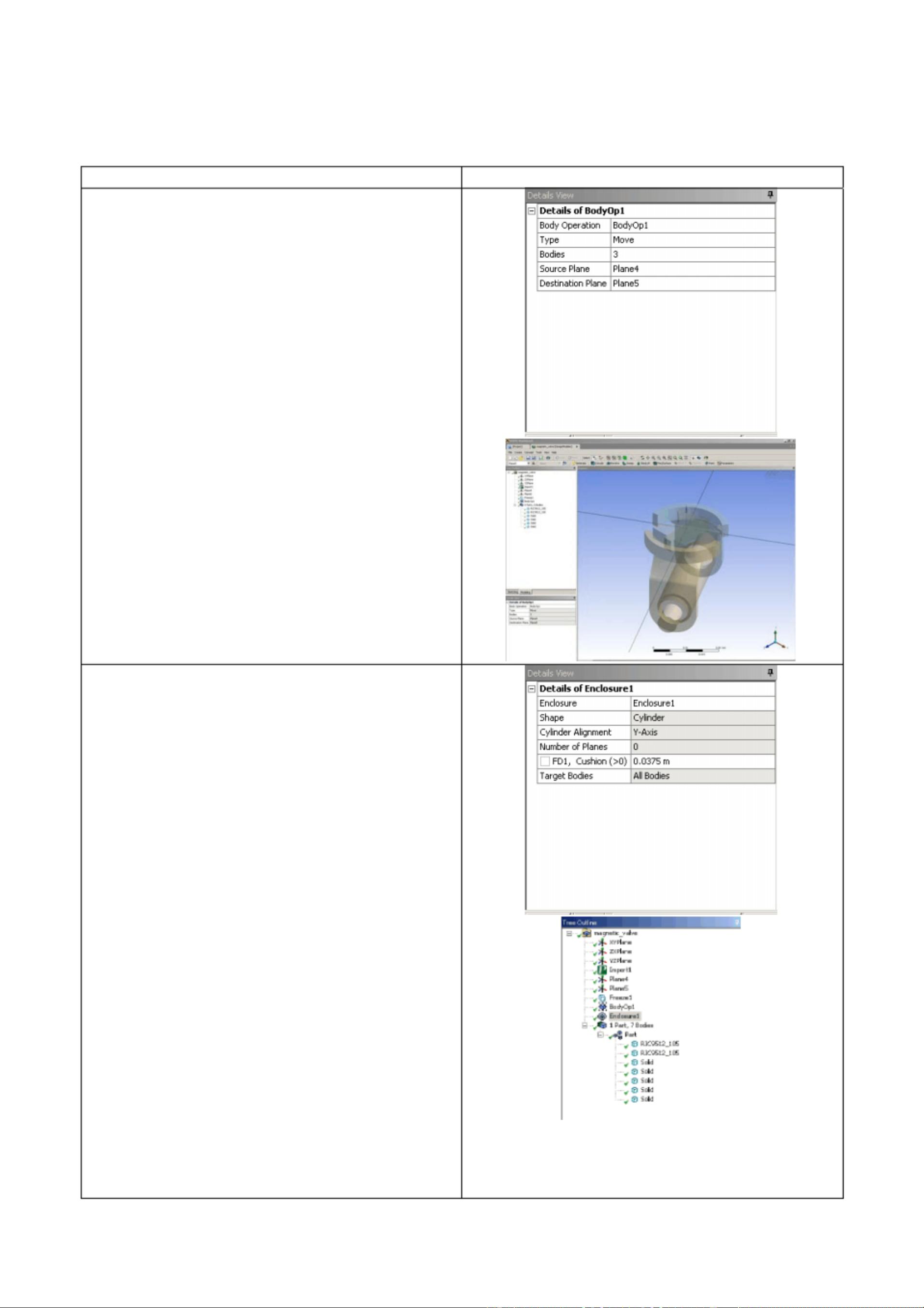
The Magnetic Valve includes a fixed and a rotating part. The rotating body has to move, as
quickly as possible, to rest in one of the 2 possible stop positions. Driving current patterns
are the input to generate suitable torques. The customer experienced different performances
of the valve for different current patterns: sometimes he got strong bumps on the mechanic
stops and failures of the valve behaviour. the customer decided to commit a simulation of
the magnetic and dynamic behaviour of the valve, instead to build a prototype.
Analysis Goal
The goal is ton achieve measure of the Magnetic Torque, as function of current and rotation
angle within a parametric approach
Owner: Enginsoft
Usage Restrictions: Freely available for use
Industry: Automotive
Application: Valve
Physics: Electromagnetics
Product(s)/Version: ANSYS-v10.1
Geometry Type(s): Solid
Geometry Format(s): Design Modeler
Model Size: 147070 Nodes, 105742 Elements
Element Type(s): Edge 117
Estimated Demo Time: 15 Minutes to show, 12 minutes running time
Customer:
Competition: Comsol, Ansoft
Challenge: Free accurate Mesh, Parametric Model, Non Linear
Magnetic Analysis
Key Features Used: Sphere of influence for meshing, BH Non Linear Curve
data import, Parametric Analysis
Workbench Simulation of a Magnetic Valve
October 10, 2006
A Guide for Magnetic Simulation of a Magnetic Valve
ANSYS Workbench Simulation
Page 2 of 23
Steps and Points to Convey. Picture Guide.
Start ANSYS Workbench Environment, and
choose “New Geometry”.
Importing of external geometry
Set the desired length unit: meters.
01) Click “File > Open > Import External
Geometry File ”.
02) Click on “Generate ” in order to confirm the
importation of the geometry.
The geometry regards a magnetic valve.
Workbench Simulation of a Magnetic Valve
October 10, 2006
A Guide for Magnetic Simulation of a Magnetic Valve
ANSYS Workbench Simulation
Steps and Points to Convey. Picture Guide.
Create a Parametric, Relative Rotation
between two groups of bodies
01) Create a local coordinate system (plane 4)
by clicking on the “New Plane ” icon in the tool
bar.
02) In “Details of Plane4 >. Type ” choose from
face in order to select the surface of interest.
03) Choose the space to the right of “Base Face ”
in Details of Plane4 and select the surface
indicated in light blue in the plot at right.
The local coordinate system “Plane 4 ” is now
visible, centered on a face vertex
04) In “Details of Plane4 >. Transform 1
(RMB)” insert an offset along X axis of –
0.00825 m.
05) In “Details of Plane4 >. Transform 1
(RMB)” insert an offset along Y axis of 0.0015
m.
06) Click Generate to create Plane4
Create another plane (Plane5).
07) In “Details of Plane5 > Type ” choose from
plane. Base plane should be set to Plane4.
08) In “Details of Plane5 >. Transform 1
(RMB)” insert a rotation about Z axis of 30 °.
09) Click Generate to create Plane5.
Page 3 of 23
Workbench Simulation of a Magnetic Valve
October 10, 2006
A Guide for Magnetic Simulation of a Magnetic Valve
ANSYS Workbench Simulation
Steps and Points to Convey. Picture Guide.
The local coordinate system “Plane 5 ” is now
visible.
10) From the tool bar menu, select “Tools >
Freeze ”.
The freezing operation is indicated when bodies
are displayed with transparency.
11) From the tool bar menu, select “Create >
Body Operation ” set “Type” to “Move” click on
the box to the right of Bodies.
12) Select the bodies highlighted at right (use
the Ctrl button to select multiple entities) and
click Apply.
Page 4 of 23
Workbench Simulation of a Magnetic Valve
October 10, 2006
A Guide for Magnetic Simulation of a Magnetic Valve
ANSYS Workbench Simulation
Steps and Points to Convey. Picture Guide.
13) In “Details of BodyOp1 ” choose the box to
the right of “Source Plane ” and pick on Plane4
in the Tree Outline.
14) In a similar fashion, set “Destination Plane ”
to Plane5.
Then click on “Generate ” to move the parts as
shown at right.
ENCLOSURE definition
01) From the tool bar menu, select “Tools >
Enclosure ” in order to insert a control
volume cylindrically shaped and aligned
to Y axis. Set the Cushion to 0.0375 m
and set “Merge Parts? ” to “Yes”.
02) Click Generate to create the enclosure
In the “Outline ” tree the just created enclosure is
now visible.
Page 5 of 23
剩余22页未读,继续阅读
诶我的狗呢
- 粉丝: 1
- 资源: 1
上传资源 快速赚钱
- 我的内容管理 收起
- 我的资源 快来上传第一个资源
- 我的收益 登录查看自己的收益
- 我的积分 登录查看自己的积分
- 我的C币 登录后查看C币余额
- 我的收藏
- 我的下载
- 下载帮助
会员权益专享
最新资源
- 2023年中国辣条食品行业创新及消费需求洞察报告.pptx
- 2023年半导体行业20强品牌.pptx
- 2023年全球电力行业评论.pptx
- 2023年全球网络安全现状-劳动力资源和网络运营的全球发展新态势.pptx
- 毕业设计-基于单片机的液体密度检测系统设计.doc
- 家用清扫机器人设计.doc
- 基于VB+数据库SQL的教师信息管理系统设计与实现 计算机专业设计范文模板参考资料.pdf
- 官塘驿林场林防火(资源监管)“空天地人”四位一体监测系统方案.doc
- 基于专利语义表征的技术预见方法及其应用.docx
- 浅谈电子商务的现状及发展趋势学习总结.doc
- 基于单片机的智能仓库温湿度控制系统 (2).pdf
- 基于SSM框架知识产权管理系统 (2).pdf
- 9年终工作总结新年计划PPT模板.pptx
- Hytera海能达CH04L01 说明书.pdf
- 数据中心运维操作标准及流程.pdf
- 报告模板 -成本分析与报告培训之三.pptx
资源上传下载、课程学习等过程中有任何疑问或建议,欢迎提出宝贵意见哦~我们会及时处理!
点击此处反馈
安全验证
文档复制为VIP权益,开通VIP直接复制
信息提交成功
评论2