没有合适的资源?快使用搜索试试~ 我知道了~
首页Robotics__Vision_and_Control_Fundamental_Algorithms_in_MATLAB英文版05-机器人导航
资源详情
资源评论
资源推荐
5
Chapter
Robot navigation is the problem of guiding a robot towards a goal.
The human approach to navigation is to make maps and erect sign-
posts, and at first glance it seems obvious that robots should oper-
ate the same way. However many robotic tasks can be achieved with-
out any map at all, using an approach referred to as reactive naviga-
tion. For example heading towards a light, following a white line on
the ground, moving through a maze by following a wall, or vacu-
uming a room by following a random path. The robot is reacting
directly to its environment: the intensity of the light, the relative
position of the white line or contact with a wall. Grey Walter’s tor-
toise Elsie from page 61 demonstrated “life-like” behaviours – she
reacted to her environment and could seek out a light source. Today
more than 5 million Roomba vacuum cleaners are cleaning floors
without using any map of the rooms they work in. The robots work
by making random moves and sensing only that they have made
contact with an obstacle.
The more familiar human-style map-based navigation is used
by more sophisticated robots. This approach supports more com-
plex tasks but is itself more complex. It imposes a number of re-
quirements, not the least of which is a map of the environment. It
also requires that the robot’s position is always known. In the next
chapter we will discuss how robots can determine their position
and create maps. The remainder of this chapter discusses the reac-
tive and map-based approaches to robot navigation with a focus on
wheeled robots operating in a planar environment.
Navigation
the process of directing a vehicle so as to reach the intended destination
IEEE Standard 172-1983
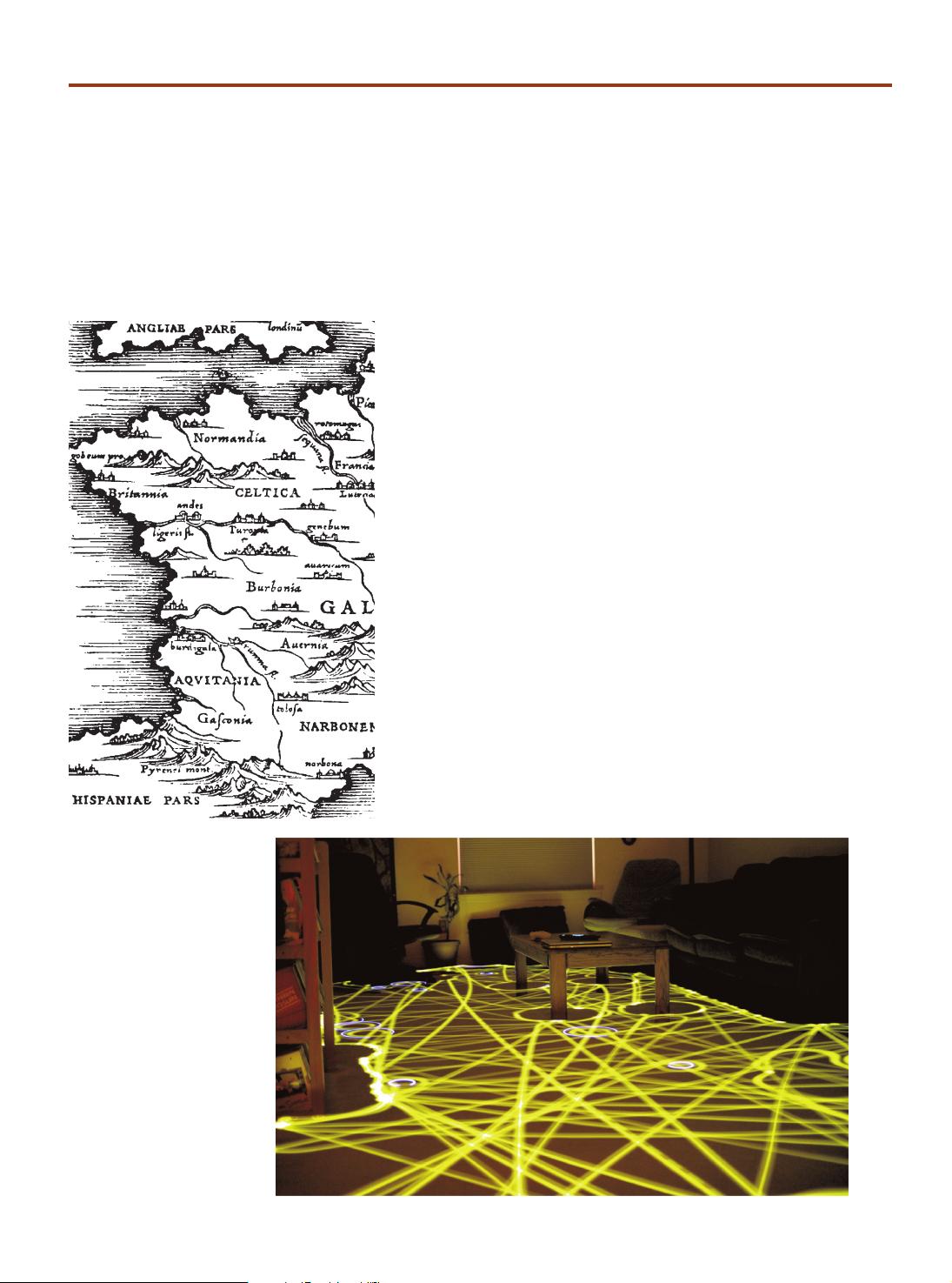
Fig. 5.1.
Time lapse photograph of a
Roomba robot cleaning a room
(photo by Chris Bartlett)
88
5.1
l
Reactive Navigation
Surprisingly complex tasks can be performed by a robot even if it has no map and no
real idea about where it is. As already mentioned robotic vacuum cleaners use only
random motion and information from contact sensors to perform a complex task as
shown in Fig. 5.1. Insects such as ants and bees gather food and return it to the nest
based on input from their senses, they have far too few neurons to create any kind of
mental map of the world and plan paths through it. Even single-celled organisms such
as flagellate protozoa exhibited goal seeking behaviours. In this case we need to revise
our earlier definition of a robot to
a goal oriented machine that can sense, p
lan and act.
The manifestation of complex behaviours by simple organisms was of interest to
early researchers in cybernetics. Grey Walter’s robotic tortoise demonstrated that it
could moves toward a light source, a behaviour known as phototaxis.
This was an
important result in the then emerging scientific field of cybernetics.
5.1.1
l
Braitenberg Vehicles
A very simple class of goal achieving robots are known as Braitenberg vehicles and are
characterised by direct connection between sensors and motors. They have no explicit
internal representation of the environment in which they operates and nor do they
make explicit plans.
Consider the problem of a robot moving in two dimensions that is seeking the
maxima of a scalar field – the field could be light intensity or the concentration of
some chemical.
The Simulink® model
>> sl_braitenberg
shown in Fig. 5.2 achieves this using a steering signal derived directly from the sensors.
More generally a
taxis
is the response
of an organism to a stimulus gradient.
Valentino Braitenberg (1926–) is an Italian-Austrian neuro-scientist and cyberneticist, and former
director at the Max Planck Institute for Biological Cybernetics in Tübingen, Germany. His 1986
book “Vehicles: Experiments in Synthetic Psychology” (image on right is of the cover this book,
published by The MIT Press, ©MIT 1984) describes reactive goal-achieving vehicles, and such
systems are now commonly known as Braitenberg Vehicles.
A Braitenberg vehicle is an automaton or robot which combines sensors, actuators and their
direct interconnection to produce goal-oriented behaviors. Grey Walter’s tortoise predates the
use of this term but is nevertheless an example of such a vehicle.
These vehicles are described as conceptually as analog circuits, but more recently small robots
based on a digital realization of the same principles have been developed.
William Grey Walter (1910–1977) was a neurophysiologist and pioneering cyberneticist born in
Kansas City, Missouri and studied at King’s College, Cambridge. Unable to obtain a research fellow-
ship at Cambridge he worked on neurophysiological research in hospitals in London and from 1939
at the Burden Neurological Institute in Bristol. He developed electroencephalographic brain topog-
raphy which used multiple electrodes on the scalp and a triangulation algorithm to determine the
amplitude and location of brain activity. (Image: courtesy of the Reuben Hoggett Collection)
Walter was influential in the then new field of cybernetics. He built robots to study how complex
reflex behavior could arise from neural interconnections. His tortoise Elsie (of the species Machina
Speculatrix) is shown, without its shell, on page 61. Built in 1948 Elsie was a three-wheeled robot ca-
pable of phototaxis that could also find its way to a recharging station. A second generation tortoise
(from 1951) is in the collection of the Smithsonian Institution. He published popular articles in “Scien-
tific American” (1950 and 1951) and a book “The Living Brain” (1953). He was badly injured in a car
accident in 1970 from which he never fully recovered. (Image courtesy Reuben Hoggett collection)
This is a fine philosophical point, the plan
could be considered to be implicit in the
details of the connections between the
motors and sensors.
This is similar to the problem of mov-
ing to a point discussed in Sect. 4.2.1.
This is similar to Braitenberg’s Vehicle 4a.
Chapter 5
·
Navigation
89
To ascend the gradient we need to estimate the gradient direction at the current
location and this requires at least two measurements of the field.
In this example we
use two sensors, bilateral sensing, with one on each side of the robot’s body. The sen-
sors are modelled by the green sensor blocks shown in Fig. 5.2 and are parameterized
by the position of the sensor with respect to the robot’s body, and the sensing function.
In this example the sensors are at ±2 units in the vehicle’s lateral or y-direction.
The field to be sensed is a simple inverse square field defined by
1 function sensor = sensorfield(x, y)
2 xc = 60; yc = 90;
3 sensor = 200./((x-xc).^2 + (y-yc).^2 + 200);
which returns the sensor value s(x, y) ∈ [0, 1] which is a function of the sensor’s posi-
tion in the plane. This particular function has a peak value at the point (60, 90).
The vehicle speed is
where s
R
and s
L
are the right and left sensor readings respectively. At the goal, where
s
R
= s
L
= 1 the velocity becomes zero.
Steering angle is based on the difference between the sensor readings
so when the field is equal in the left- and right-hand sensors the robot moves straight ahead.
We start the simulation from the Simulink® menu or the command line
>> sim('sl_braitenberg');
and the path of the robot is shown in Fig. 5.3. The starting pose can be changed through
the parameters of the Bicycle block. We see that the robot turns toward the goal and
slows down as it approaches, asymptotically achieving the goal position.
This particular sensor-action control law results in a specific robotic behaviour. We
could add additional logic to the robot to detect that it had arrived near the goal and
then switch to a stopping behaviour. An obstacle would block this robot since its only
behaviour is to steer toward the goal, but an additional behaviour could be added to
handle this case and drive around an obstacle. We could add another behaviour to
search randomly for the source if none was visible. Grey Walter’s tortoise had four
behaviours and switching was based on light level and a touch sensor.
Fig. 5.2. The Simulink® model
sl_braitenberg drives the
vehicle toward the maxima of a
provided scalar function. The ve-
hicle plus controller is an example
of a Braitenberg vehicle
We can make the measurements simul-
taneously using two spatially separated
sensors or from one sensor over time as
the robot moves.
Similar strategies are used by moths
whose two antennae are exquisitely
sensitive odor detectors that are used
to steer a male moth toward a phero-
mone emitting female.
5.1 · Reactive Navigation
90
Multiple behaviours and the ability to switch between them leads to an approach
known as behaviour-based robotics. The subsumption architecture was proposed as a
means to formalize the interaction between different behaviours. Complex, some might
say intelligent looking, behaviours can be manifested by such systems. However as more
behaviours are added the complexity of the system grows rapidly and interactions
between behaviours become more complex to express and debug. Ultimately the pen-
alty of not using a map becomes too great.
5.1.2
l
Simple Automata
Another class of reactive robots are known as bugs – simple automata that perform
goal seeking in the presence of non-driveable areas or obstacles. There are a large
number of bug algorithms and they share the ability to sense when they are in proxim-
ity to an obstacle. In this respect they are similar to the Braitenberg class vehicle, but
the bug includes a state machine and other logic in between the sensor and the motors.
The automata have memory which our earlier Braitenberg vehicle lacked.
In this
section we will investigate a specific bug algorithm known as bug2.
We start by loading an obstacle field to challenge the robot
>> load map1
which defines a 100 × 100 matrix variable map in the workspace. The elements are
zero or one representing free space or obstacle respectively and this is shown in Fig. 5.4.
Tools to generate such maps are discussed on page 92. This matrix is an example of an
occupancy grid which will be discussed further in the next section.
At this point we state some assumptions. Firstly, the robot operates in a grid world
and occupies one grid cell. Secondly, the robot does not have any non-holonomic con-
straints and can move to any neighbouring grid cell. Thirdly, it is able to determine its
position on the plane which is a non-trivial problem that will be discussed in detail in
Chap. 6. Finally, the robot can only sense its immediate locale and the goal. The robot
does not use the map – the map is used by the simulator to provide sensory inputs to
the robot.
We create an instance of the bug2 class
>> bug = Bug2(map);
and the goal is
>> bug.goal = [50; 35];
Fig. 5.3.
Path of the Braitenberg vehicle
moving toward (and past) the
maximum of a 2D scalar field
whose magnitude is shown
color coded
Braitenberg’s book describes a series of
increasingly complex vehicles, some of
which incorporate memory. However
the term
Braitenberg vehicle
has be-
come associated with the simplest ve-
hicles he described.
Chapter 5
·
Navigation
剩余19页未读,继续阅读
qq_14903801
- 粉丝: 5
- 资源: 25
上传资源 快速赚钱
- 我的内容管理 收起
- 我的资源 快来上传第一个资源
- 我的收益 登录查看自己的收益
- 我的积分 登录查看自己的积分
- 我的C币 登录后查看C币余额
- 我的收藏
- 我的下载
- 下载帮助
会员权益专享
最新资源
- stc12c5a60s2 例程
- Android通过全局变量传递数据
- c++校园超市商品信息管理系统课程设计说明书(含源代码) (2).pdf
- 建筑供配电系统相关课件.pptx
- 企业管理规章制度及管理模式.doc
- vb打开摄像头.doc
- 云计算-可信计算中认证协议改进方案.pdf
- [详细完整版]单片机编程4.ppt
- c语言常用算法.pdf
- c++经典程序代码大全.pdf
- 单片机数字时钟资料.doc
- 11项目管理前沿1.0.pptx
- 基于ssm的“魅力”繁峙宣传网站的设计与实现论文.doc
- 智慧交通综合解决方案.pptx
- 建筑防潮设计-PowerPointPresentati.pptx
- SPC统计过程控制程序.pptx
资源上传下载、课程学习等过程中有任何疑问或建议,欢迎提出宝贵意见哦~我们会及时处理!
点击此处反馈
安全验证
文档复制为VIP权益,开通VIP直接复制
信息提交成功
评论0