没有合适的资源?快使用搜索试试~ 我知道了~
首页g-sensor规格书资料
g-sensor规格书资料
需积分: 50 10 下载量 40 浏览量
更新于2023-03-16
评论
收藏 1.1MB PDF 举报
g-sensor规格书资料,mcube品牌计步芯片,mcube品牌计步芯片
资源详情
资源评论
资源推荐
MC3413 3-Axis Accelerometer Preliminary Datasheet
mCube Proprietary. APS-048-0029v1.7 1 / 47
© 2014 mCube Inc. All rights reserved.
GENERAL DESCRIPTION
The MC3413 is a low-noise, integrated
digital output 3-axis accelerometer with a
feature set optimized for cell phones and
consumer product motion sensing.
Applications include user interface control,
gaming motion input, electronic compass tilt
compensation for cell phones, game
controllers, remote controls and portable
media products.
Low noise and low power are inherent in
the monolithic fabrication approach, where
the MEMS accelerometer is integrated in a
single-chip with the electronics integrated
circuit.
In the MC3413 the internal sample rate can
be set from 0.25 to 256 samples / second.
Specific tap or sample acquisition
conditions can trigger an interrupt to a
remote MCU. Alternatively, the device
supports the reading of sample and event
status via polling.
FEATURES
Range, Sampling & Power
±2,4,8,12 or 16g ranges
8, 10 or 14-bit resolution
0.25 - 256 samples/sec
50 - 130 μA typical current
Event Detection
Low-noise architecture minimizes
false triggering
Independent X,Y,Z Tap
Simple System Integration
I2C interface, up to 400 kHz
2 × 2 × 0.92 mm 12-pin package
‒ Pin-compatible to Bosch BMA2xx
Single-chip 3D silicon MEMS
<200µg / √Hz noise
MC3413 3-Axis Accelerometer Preliminary Datasheet
mCube Proprietary. APS-048-0029v1.7 2 / 47
© 2014 mCube Inc. All rights reserved.
TABLE OF CONTENTS
1 Order Information ............................................................................................................. 4
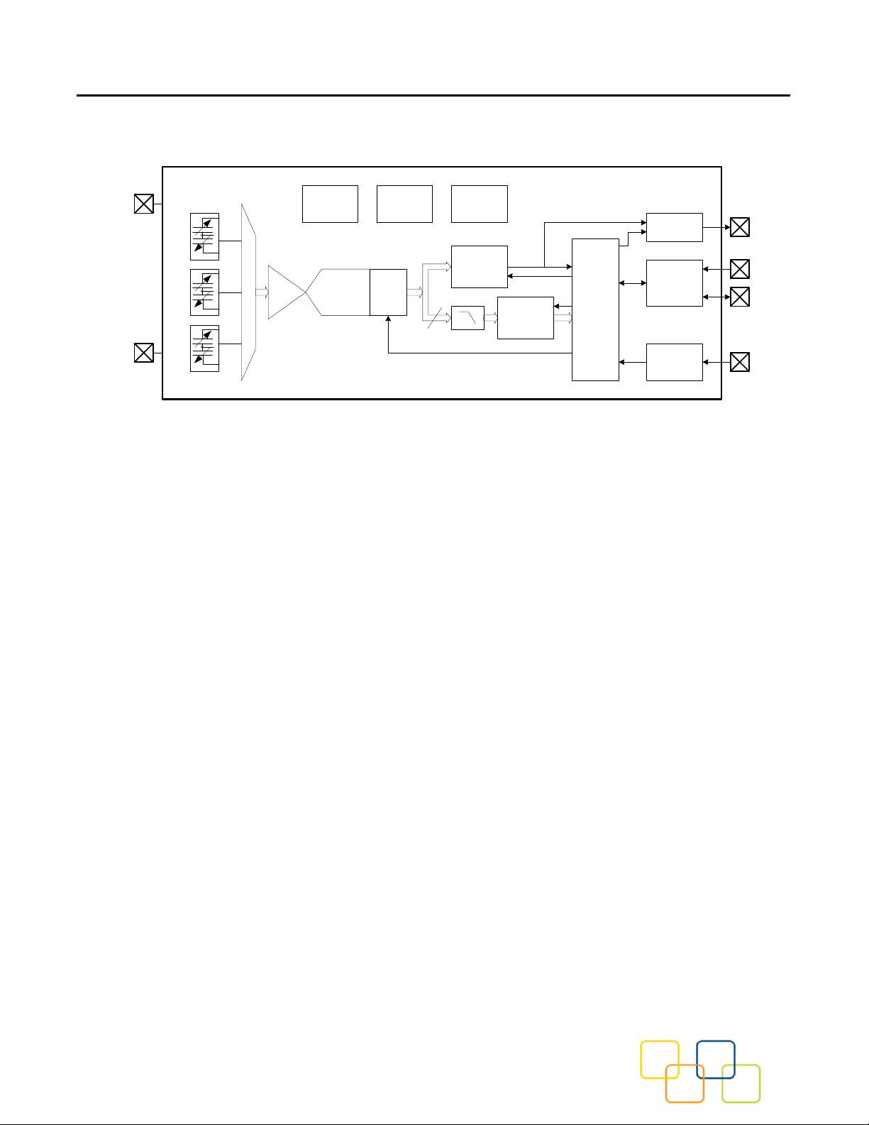
2 Functional Block Diagram ................................................................................................ 5
3 Packaging and Pin Description ........................................................................................ 6
3.1 Package Outline ................................................................................................................... 6
3.2 Package Orientation ............................................................................................................. 7
3.3 Pin Description ..................................................................................................................... 8
3.4 Typical Application Circuits .................................................................................................. 9
3.5 Tape and Reel ................................................................................................................... 11
4 Specifications ................................................................................................................. 13
4.1 Absolute Maximum Ratings ................................................................................................ 13
4.2 Sensor Characteristics ....................................................................................................... 14
4.3 Electrical and Timing Characteristics .................................................................................. 15
4.3.1 Electrical Power and Internal Characteristics ....................................................... 15
4.3.2 I2C Electrical Characteristics ............................................................................... 16
4.3.3 I2C Timing Characteristics ................................................................................... 17
5 General Operation ......................................................................................................... 18
5.1 Sensor Sampling ................................................................................................................ 18
5.2 Offset and Gain Calibration ................................................................................................ 18
5.3 Tap Detection ..................................................................................................................... 18
6 Operational States ......................................................................................................... 19
7 Operational State Flow .................................................................................................. 20
8 Interrupts ........................................................................................................................ 21
8.1 Enabling and Clearing Interrupts ........................................................................................ 21
8.2 ACQ_INT Interrupt ............................................................................................................. 21
9 Sampling ........................................................................................................................ 22
9.1 Continuous Sampling ......................................................................................................... 22
10 I2C Interface .................................................................................................................. 23
10.1 Physical Interface ............................................................................................................... 23
10.2 Timing ................................................................................................................................ 24
10.3 I2C Message Format .......................................................................................................... 24
10.4 Watchdog Timer ................................................................................................................. 25
MC3413 3-Axis Accelerometer Preliminary Datasheet
mCube Proprietary. APS-048-0029v1.7 3 / 47
© 2014 mCube Inc. All rights reserved.
11 Register Interface .......................................................................................................... 26
11.1 Register Summary ............................................................................................................. 27
11.2 SR Status Register ............................................................................................................. 29
11.3 OPSTAT Device Status Register ........................................................................................ 30
11.4 INTEN Interrupt Enable Register ........................................................................................ 31
11.5 MODE Register .................................................................................................................. 32
11.6 SRTFR Sample Rate and Tap Feature Register ................................................................ 33
11.7 TAPEN Tap Control Register ............................................................................................. 34
11.8 TTTRX,TTTRY, TTTRZ X, Y and Z Tap Duration and Threshold Registers ....................... 35
11.9 XOUT_EX, YOUT_EX & ZOUT_EX X, Y, Z-Axis Acceleration Registers ........................... 36
11.10 OUTCFG Output Configuration Register ............................................................................ 37
11.11 X-Axis Offset Registers ...................................................................................................... 38
11.12 Y-Axis Offset Registers ...................................................................................................... 39
11.13 Z-Axis Offset Registers ...................................................................................................... 40
11.14 X-Axis Gain Registers ........................................................................................................ 41
11.15 Y-Axis Gain Registers ........................................................................................................ 42
11.16 Z-Axis Gain Registers ........................................................................................................ 43
11.17 PCODE Product Code........................................................................................................ 44
12 Index of Tables .............................................................................................................. 45
13 Revision History ............................................................................................................. 46
14 Legal .............................................................................................................................. 47
MC3413 3-Axis Accelerometer Preliminary Datasheet
mCube Proprietary. APS-048-0029v1.7 4 / 47
© 2014 mCube Inc. All rights reserved.
1 ORDER INFORMATION
Table 1. Order Information
Part Number
Resolution
Order Number
Package
Shipping
MC3413
8 to 14-bit
MC3413
VLGA-12
Tape & Reel, 5Ku
MC3413 3-Axis Accelerometer Preliminary Datasheet
mCube Proprietary. APS-048-0029v1.7 5 / 47
© 2014 mCube Inc. All rights reserved.
2 FUNCTIONAL BLOCK DIAGRAM
Event
Detection
A/D Converter
(Sigma Delta)
C to V
VPP
VDD/VDDIO
GND
Regulators
and Bias
Oscillator/
Clock
Generator
Mode Logic
I2C Slave
Interface
Interrupt
X
Y
Z
OTP
Memory
Registers
(64 x 8)
SCL
SDA
INTN
Offset/
Gain
Adjust
X,Y,Z
data paths
Sensors
Range &
Scale
Figure 1. Block Diagram
剩余46页未读,继续阅读
芯不设房
- 粉丝: 0
- 资源: 1
上传资源 快速赚钱
- 我的内容管理 收起
- 我的资源 快来上传第一个资源
- 我的收益 登录查看自己的收益
- 我的积分 登录查看自己的积分
- 我的C币 登录后查看C币余额
- 我的收藏
- 我的下载
- 下载帮助
会员权益专享
最新资源
- stc12c5a60s2 例程
- Android通过全局变量传递数据
- c++校园超市商品信息管理系统课程设计说明书(含源代码) (2).pdf
- 建筑供配电系统相关课件.pptx
- 企业管理规章制度及管理模式.doc
- vb打开摄像头.doc
- 云计算-可信计算中认证协议改进方案.pdf
- [详细完整版]单片机编程4.ppt
- c语言常用算法.pdf
- c++经典程序代码大全.pdf
- 单片机数字时钟资料.doc
- 11项目管理前沿1.0.pptx
- 基于ssm的“魅力”繁峙宣传网站的设计与实现论文.doc
- 智慧交通综合解决方案.pptx
- 建筑防潮设计-PowerPointPresentati.pptx
- SPC统计过程控制程序.pptx
资源上传下载、课程学习等过程中有任何疑问或建议,欢迎提出宝贵意见哦~我们会及时处理!
点击此处反馈
安全验证
文档复制为VIP权益,开通VIP直接复制
信息提交成功
评论0