没有合适的资源?快使用搜索试试~ 我知道了~
首页OGRE 3D 1.7 Beginner's Guide 第二章 中文翻译
资源详情
资源评论
资源推荐
[声明:本人仅仅英语四级水平,因为喜欢翻译和喜欢 Ogre,翻译以下文字,如果哪里有错误或不足还望
大虾们见谅,如果您发现有什么错误,请把问题发送到 whistleofmysong@gmail.com ,我将尽快的改正。
想到可能对新手有些许帮助,所以对别人是个帮助,对自己也是个鼓励~^_^ ]
2 The Ogre Scene Graph
【 第二章 Ogre 之场景绘图】
This chapter will introduce us to the concept of a scene graph and how we can use its functions to
create complex scenes
【 这章将会介绍给我们场景绘图的一些概念和如何使用函数创造一个复杂的场景。 】
In this chapter, we will:
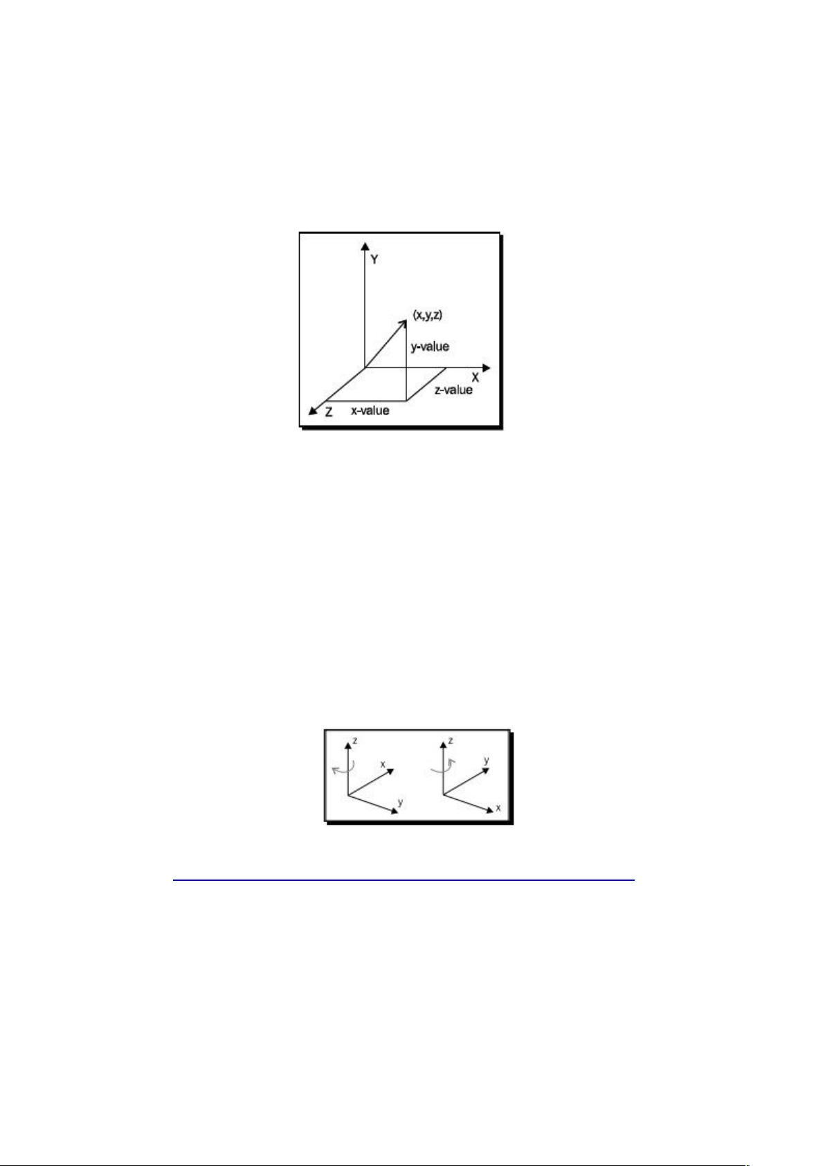
Learn the three basic operations in 3D space
How a scene graph is organized
The different 3D spaces we can operate in
let's get on with it.
【
在这章,我们将会:
学习在 3D 空间中三个基本的操作。
一个场景绘图是如何被组织的。
我们可以操作的不同的 3D 空间。
那么,就让我们开始吧。
】
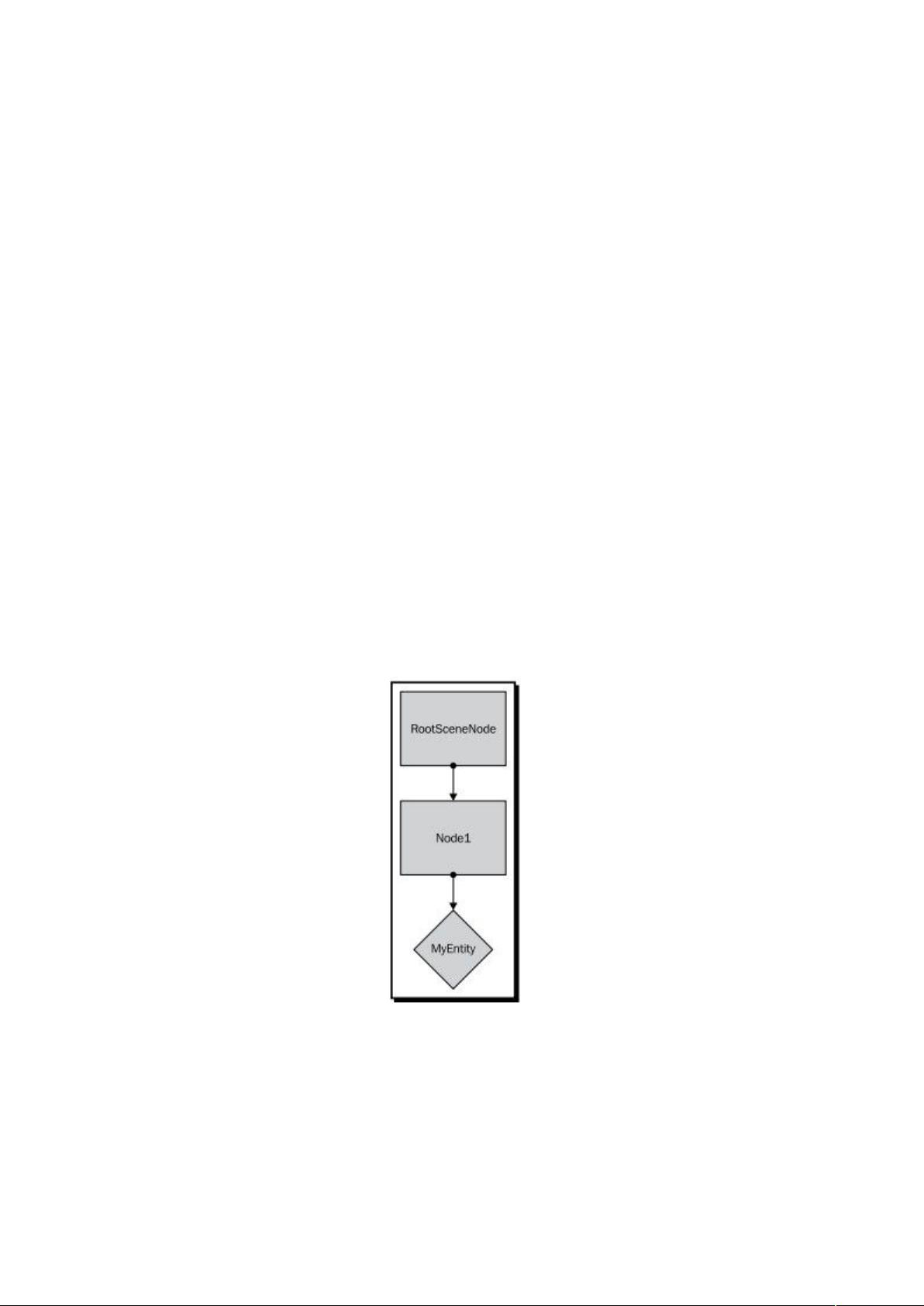
Creating a scene node
【 创建一个场景结点。 】
In the last chapter, Chapter 1, Installing Ogre 3D, we loaded a 3D model and attached it to our
scene. Now we will learn how to create a new scene node and attach our 3D model to it.
【 在上一章中(第一章 创建 Ogre 3D),,我们加载了一个 3D 模型并且把它绑定到我们
的场景上。现在我们将会学习如何创建一个新的场景结点并且把我们的 3D 模型绑定到结
点上。 】
Time for action – creating a scene node with Ogre 3D
【 实践时刻 — 用 Ogre3D 创建一个场景结点 】
We are going to use the code from Chapter 1, Installing Ogre 3D modify it to create a new scene
node, and attach it to the scene. We will follow these steps:
【 我们将会使用第一章的代码,修改第一章的代码以创建一个新的场景结点,并且把他绑
定到一个场景结点上。我们将会做以下步骤:】
1.In the old version of our code, we had the following two lines in the createScene() function:
【 在我们老版本的代码中,我们在 createScene() 函数中存在以下两行。】
Ogre::Entity* ent = mSceneMgr->createEntity("MyEntity","Sinbad.mesh");
mSceneMgr->getRootSceneNode()->attachObject(ent);
2. Replace the last line with the following:
【 用以下代码替换函数中的最后一行。 】
Ogre::SceneNode* node = mSceneMgr->createSceneNode("Node1");
3. Then add the following two lines; the order of those two lines is irrelevant for
the resulting scene:
【 然后添加以下两行;这两行代码的添加顺序对场景的效果没有影响。 】
mSceneMgr->getRootSceneNode()->addChild(node);
node->attachObject(ent);
4. Compile and start the application.
【 编译并且运行应用程序。 】
5. You should see the same screen you get when starting the application from
Chapter 1.
【 当你运行应用程序,你应会看到和你第一章一样的场景。】
What just happened?
【 刚刚发生了什么?】
We created a new scene node named Node1. Then we added the scene node to the root
scene node. After this, we attached our previously created 3D model to the newly created
scene node so it would be visible.
【 我们创建了一个新的命名为 Node1 的场景结点。然后我们添加这个场景结点到根结点。
在这之后,我们绑定之前的 3D 模型到我们新创建的结点上面,这样就可以看到效果了。
】
How to work with the RootSceneNode
【 如何使用场景根结点 】
The call mSceneMgr->getRootSceneNode() returns the root scene node. This scene node is a
member variable of the scene manager. When we want something to be visible, we need to attach
it to the root scene node or a node which is a child or a descendent in any way. In short, there
needs to be a chain of child relations from the root node to the node; otherwise it won't be
rendered. As the name suggests, the root scene node is the root of the scene. So the entire scene
will be, in some way, attached to the root scene node. Ogre 3D uses a so-called scene graph to
organize the scene.
【 调用 mSceneMgr->getRootSceneNode() 函数将会返回场景的根结点。这个场景结点是场
景管理器的一个成员变量。当我们想要什么显示的时候,我们需要以一种方式把它绑定到
场景根结点上或者一个派生类或子类的结点上。简而言之,子结点需要和根结点保持结点
与结点之间的联系,否则的话,子结点上的模型就得不到渲染。就像变量名所暗示的那样
场景根结点是场景的根。因此整个场景将会以某种方式绑定到场景的根结点上。Ogre 3D
使用了所谓的场景绘图的方式来组织场景。 】
This graph is like a tree,
it has one root, the root scene node, and each node can have children. We already have used this
characteristc when we called mSceneMgr->getRootSceneNode()->addChild(node);. There we
added the created scene node as a child to the root. Directly afterwards, we added another kind of
child to the scene node with node->attachObject(ent);. Here, we added an entity to the scene node.
We have two different kinds of objects we can add to a scene node. Firstly, we have other scene
nodes, which can be added as children and have children themselves. Secondly, we have entity
that we want rendered. Entity aren't children and can't have children themselves. They are data
objects which are associated with the node and can be thought of as leaves of the tree. There are a
lot of other things we can add to a scene, like lights, particle systems, and so on. We will later
learn what these things are and how to use them. Right now, we only need entity. Our current
scene graph looks like the following:
【 这个绘图的方式就好像一棵树一样。它只有一个根(也就是场景根结点),并且每个结
点 都 可 以 有 子 结 点 。 我 们 已 经 使 用 了 这 一 特 性 当 我 们 调 用 mSceneMgr-
>getRootSceneNode()->addChild(node) 的时候。我们把创建好的场景结点当做场景根结点的
子结点。在这之后,我们添加了 node->attachObject(ent) 使另一种类型添加到场景结点。这
里,我们添加一个实体到场景结点。我们现在有两种不同的可以添加到场景结点的对象。
首先,创建可以被添加为子结点或者可以继续为自己添加子结点的结点。然后,我们我们
创建我们想要渲染的实体。实体不是子结点,它们也不可能有子结点。它们有数据对象可
以被关联上结点也可以被认为是树上的叶子。我们稍晚将会学习它们到底是什么和如何使
用它们。现在,我们只需要实体。我们当前的场景绘图方式就好像下图一样。】
The first thing we need to understand is what a scene graph is and what it does. A scene graph is
used to represent how different parts of a scene are related to each other in 3D space.
【 首先我们需要理解的是什么是场景结点并且他们是干什么的。一个场景绘图就是用来代
替在 3D 空间中不同部分的场景是如何相互关联在一起的。 】
3D space
Ogre 3D is a 3D rendering engine, so we need to understand some basic 3D concepts. The
most basic construct in 3D is a vector, which is represented by an ordered triple (x,y,z)
【 Ogre 3D 是一个 3D 渲染引擎,所以我们需要一些基本的 3D 概念。在 3D 上最基础的结
构就是向量,这个向量中有次序的包含着(x,y,z)。 】
Each position in a 3D space can be represented by such a triple using the Euclidean coordinat ion
system for three dimensions. It is important to know that there are different kinds of coordinate
systems in 3D space. The only difference between the systems is the orientation of the axis and the
positive rotation direction. There are two systems that are widely used, namely, the left-handed
and the right-handed versions. In the following image, we see both systems—on the left side, we
see the left-handed version; and on the right side, we see the right-handed one.
【 在 3D 空间的每个位置都可以被欧几里德三维坐标系的一个三维坐标表示。我们要强调
一下在 3D 表示方面有不同的坐标体系。而这些体系之间的不同就是主轴的方向和选装的
正方向。现在主流的有两种体系,左手坐标系和右手坐标系。在下面的图中,我们看到两
种体系— 在左边我们看到的是左手坐标系;在右边我们看到的是右手坐标系。 】
Source: http://en.wikipedia.org/wiki/File:Cartesian_coordinate_system_handedness.svg
The names left-and right-handed are based on the fact that the orientation of the axis can be
reconstructed using the left and right hand. The thumb is the x-axis, the index finger the y-axis,
and the middle finger the z-axis. We need to hold our hands so that we have a ninety-degree angle
between thumb and index finger and also between middle and index finger. When using the right
hand, we get a right-handed coordination system. When using the left hand, we get the left-handed
version.
【 左手和右手坐标系名字的由来是基于他们主轴方向的不同,方向是左手和右手来决定创
建的。大拇指是 X 轴,食指是 Y 轴,而中指是 Z 轴。我们需要张开手使大拇指,食指和中
指之间保持 90 度角。当使用右手时,我们就可以得到一个右手坐标系。当使用左手时,我
们就可以得到一个右手坐标系】
Ogre uses the right-handed system, but rotates it so that the positive part of the x-axis is pointing
right and the negative part of the x-axis points to the left. The y-axis is pointing up and the z-axis
is pointing out of the screen and it is known as the y-up convention. This sounds irritating at first,
but we will soon learn to think in this coordinate system. The Website
http://viz.aset.psu.edu/gho/sem_notes/3d_fundamentals/html/3d_coordinates.html contains a
rather good picture-based explanation of the different coordination systems and how they relate to
each other.
【 Ogre 使用的是右手坐标系,但是旋转坐标系使 X 轴的正半轴指向右并且 X 轴的负半轴
指 向 左 。 Y 轴 ( 正 半 轴 ) 指 向 上 , Z 轴 ( 正 半 轴 ) 垂 直 于 屏 幕 向 外 , 这 被 称 为 y-up
convention。这开始会使我们很不适应。但是我们不久将会在这样的坐标系下学习研究
Ogre 。 这 个 网 址 http://viz.aset.psu.edu/gho/sem_notes/3d_fundamentals/html/
3d_coordinates.html 有能更好展示不同坐标系之间的不同和联系的图片解释。 】
Scene graph
【场景绘图】
A scene graph is one of the most used concepts in graphics programming. Simply put, it's a way to
store information about a scene. We already discussed that a scene graph has a root and is
organized like a tree. But we didn't touch on the most important function of a scene graph. Each
node of a scene graph has a list of its children as well as a transformation in the 3D space. The
transformation is composed of three aspects, namely, the position, the rotation, and the scale. The
position is a triple (x,y,z), which obviously describes the position of the node in the scene. The
rotation is stored using a quaternion, a mathematical concept for storing rotations in 3D space, but
we can think of rotations as a single floating point value for each axis, describing how the node is
rotated using radians as units. Scaling is quite easy; again, it uses a triple (x,y,z), and each part of
the triple is simply the factor to scale the axis with.
【 场景绘图是在图形化编程领域最被广泛使用的概念之一。简单的说,这是存储场景信息
的一种方式。我们已经讨论过场景绘图必须有一个根结点而且是树形结构的。但是我们还
没有涉及场景绘图中最重要的函数。每个场景结点既可有子结点也可以在 3D 空间变换的
函数。这些变换可以说由三方面组成,就是—— 位置变换(position),旋转变换(rotation)和
缩放(scale)变换。坐标点的(x,y,z),明确的描述了结点在场景中的位置。旋转是使用四元数
来储存的,四元数是 3D 空间存贮旋转的一个数学概念,但是我们可以认为旋转就是每个
坐标轴一个的浮点数,描述了结点以弧度为单位的旋转。缩放就比较简单了,同样的,就
是它使用了一个(x,y,z)的数组,并且数组的每一部分就是对应坐标轴的缩放比例。 】
The important thing about a scene graph is that the transformation is relative to the parent
of the node. If we modify the orientation of the parent, the children will also be affected
by this change. When we move the parent 10 units along the x-axis, all children will also be
moved by 10 units along the x-axis. The final orientation of each child is computed using the
orientation of all parents. This fact will become clearer with the next diagram.
剩余31页未读,继续阅读
chinarpgmaker
- 粉丝: 2
- 资源: 17
上传资源 快速赚钱
- 我的内容管理 收起
- 我的资源 快来上传第一个资源
- 我的收益 登录查看自己的收益
- 我的积分 登录查看自己的积分
- 我的C币 登录后查看C币余额
- 我的收藏
- 我的下载
- 下载帮助
会员权益专享
最新资源
- stc12c5a60s2 例程
- Android通过全局变量传递数据
- c++校园超市商品信息管理系统课程设计说明书(含源代码) (2).pdf
- 建筑供配电系统相关课件.pptx
- 企业管理规章制度及管理模式.doc
- vb打开摄像头.doc
- 云计算-可信计算中认证协议改进方案.pdf
- [详细完整版]单片机编程4.ppt
- c语言常用算法.pdf
- c++经典程序代码大全.pdf
- 单片机数字时钟资料.doc
- 11项目管理前沿1.0.pptx
- 基于ssm的“魅力”繁峙宣传网站的设计与实现论文.doc
- 智慧交通综合解决方案.pptx
- 建筑防潮设计-PowerPointPresentati.pptx
- SPC统计过程控制程序.pptx
资源上传下载、课程学习等过程中有任何疑问或建议,欢迎提出宝贵意见哦~我们会及时处理!
点击此处反馈
安全验证
文档复制为VIP权益,开通VIP直接复制
信息提交成功
评论0