没有合适的资源?快使用搜索试试~ 我知道了~
首页ADIS16405数据手册
资源详情
资源评论
资源推荐
Tri-Axis Inertial Sensor
with Magnetometer
ADIS16405
Rev. 0
Information furnished by Analog Devices is believed to be accurate and reliable. However, no
responsibility is assumed by Analog Devices for its use, nor for any infringements of patents or other
rights of third parties that may result from its use. Specifications subject to change without notice. No
license is granted by implication or otherwise under any patent or patent rights of Analog Devices.
Trademarks and registered trademarks are the property of their respective owners.
One Technology Way, P.O. Box 9106, Norwood, MA 02062-9106, U.S.A.
Tel: 781.329.4700 www.analog.com
Fax: 781.461.3113 ©2009 Analog Devices, Inc. All rights reserved.
FEATURES
Tri-axis, digital gyroscope with digital range scaling
±75°/sec, ±150°/sec, ±300°/sec settings
Tri-axis, ±18 g digital accelerometer
Tri-axis, ±2.5 gauss digital magnetometer
220 ms start-up time
Factory-calibrated sensitivity, bias, and axial alignment
Calibration temperature range: −40°C to +85°C
Digitally controlled bias calibration
Digitally controlled sample rate, up to 819.2 SPS
External clock input enables sample rates up to 1200 SPS
Digitally controlled filtering
Programmable condition monitoring
Auxiliary digital input/output
Digitally activated self-test
Programmable power management
Embedded temperature sensor
SPI-compatible serial interface
Auxiliary, 12-bit ADC input and DAC output
Single-supply operation: 4.75 V to 5.25 V
2000 g shock survivability
Operating temperature range: −40°C to +105°C
APPLICATIONS
Unmanned aerial vehicles
Platform control
Digital compassing
Navigation
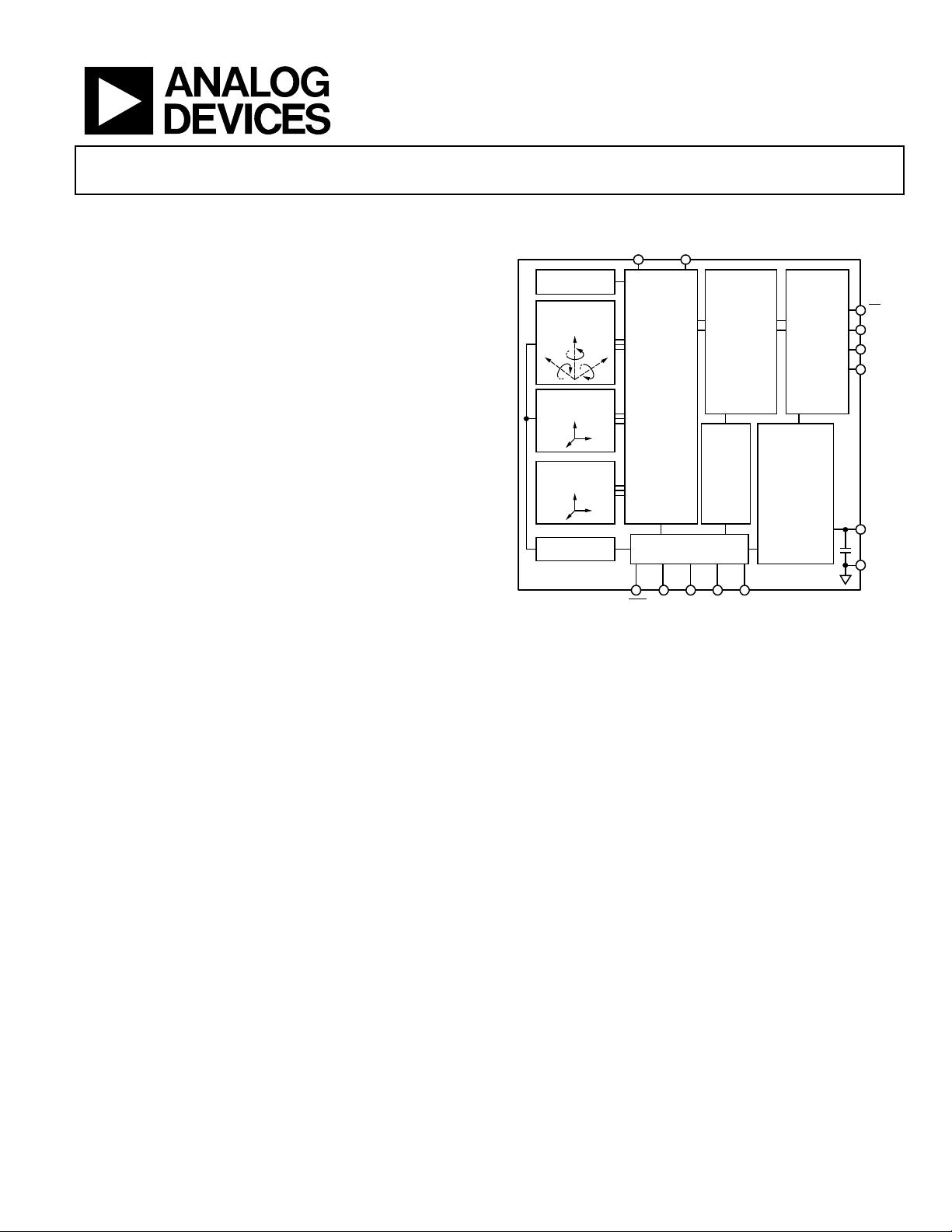
FUNCTIONAL BLOCK DIAGRAM
TRI-AXIS MEMS
ANGULAR RATE
SENSOR
SIGNAL
CONDITIONING
AND
CONVERSION
CALIBRATION
AND
DIGITAL
PROCESSING
DIGITAL
CONTROL
POWER
MANAGEMENT
OUTPUT
REGISTERS
AND SPI
INTERFACE
A
UX_
ADC
AUX_
DAC
RST
CS
SCLK
DIN
DOUT
VCC
GND
DIO4/
CLKIN
SELF-TEST
ADIS16405
TRI-AXIS MEMS
ACCELERATION
SENSOR
TRI-AXIS
MAGNETIC
SENSOR
TEMPERATURE
SENSOR
ALARMS
DIO3DIO2DIO1
07907-001
Figure 1.
GENERAL DESCRIPTION
The ADIS16405 iSensor® is a complete inertial system that includes
a tri-axis gyroscope, a tri-axis accelerometer, and a tri-axis mag-
netometer. The ADIS16405 combines industry-leading iMEMS®
technology with signal conditioning that optimizes dynamic
performance. The factory calibration characterizes each sensor
for sensitivity, bias, alignment, and linear acceleration (gyroscope
bias). As a result, each sensor has its own dynamic compensation
for correction formulas that provide accurate sensor measurements
over a temperature range of −40°C to +85°C. The magnetometers
employ a self-correction function to provide accurate bias
performance over temperature as well.
The ADIS16405 provides a simple, cost-effective method for
integrating accurate, multi-axis inertial sensing into industrial
systems, especially when compared with the complexity and
investment associated with discrete designs.
All necessary motion testing and calibration are part of the produc-
tion process at the factory, greatly reducing system integration time.
Tight orthogonal alignment simplifies inertial frame alignment
in navigation systems. An improved SPI interface and register
structure provide faster data collection and configuration control.
By using a compatible pinout and the same package as the
ADIS1635x and ADIS1636x families, upgrading to the ADIS16405
requires only firmware changes to accommodate additional sensors
and register map updates.
This compact module is approximately 23 mm × 23 mm × 23 mm
and provides a flexible connector interface, which enables multiple
mounting orientation options.
ADIS16405
Rev. 0 | Page 2 of 16
TABLE OF CONTENTS
Features .............................................................................................. 1
Applications ....................................................................................... 1
Functional Block Diagram .............................................................. 1
General Description ......................................................................... 1
Revision History ............................................................................... 2
Specifications ..................................................................................... 3
Timing Specifications .................................................................. 5
Timing Diagrams .......................................................................... 5
Absolute Maximum Ratings ............................................................ 6
ESD Caution .................................................................................. 6
Pin Configuration and Function Descriptions ............................. 7
Typical Performance Characteristics ............................................. 8
Theory of Operation .........................................................................9
Basic Operation .............................................................................9
Reading Sensor Data .....................................................................9
Device Configuration ...................................................................9
Burst Mode Data Collection ........................................................9
Output Data Registers ............................................................... 11
Calibration ................................................................................... 11
Operational Control ................................................................... 12
Input/Output Functions ............................................................ 13
Diagnostics .................................................................................. 14
Outline Dimensions ....................................................................... 16
Ordering Guide .......................................................................... 16
REVISION HISTORY
3/09—Revision 0: Initial Version
ADIS16405
Rev. 0 | Page 3 of 16
SPECIFICATIONS
T
A
= −40°C to +85°C, VCC = 5.0 V, angular rate = 0°/sec, dynamic range = ±300°/sec, ±1 g, unless otherwise noted.
Table 1.
Parameter Test Conditions Min Typ Max Unit
GYROSCOPES
Dynamic Range ±300 ±350 °/sec
Initial Sensitivity Dynamic range = ±300°/sec 0.0495 0.05 0.0505 °/sec/LSB
Dynamic range = ±150°/sec 0.025 °/sec/LSB
Dynamic range = ±75°/sec 0.0125 °/sec/LSB
Sensitivity Temperature Coefficient −40°C ≤ T
A
≤ +85°C ±40 ppm/°C
Misalignment Axis-to-axis, ∆ = 90° ideal ±0.05 Degrees
Axis-to-frame (package) ±0.5 Degrees
Nonlinearity Best fit straight line 0.1 % of FS
Initial Bias Error 1 σ ±3 °/sec
In-Run Bias Stability 1 σ, SMPL_PRD = 0x01 0.007 °/sec
Angular Random Walk 1 σ, SMPL_PRD = 0x01 2.0 °/√hr
Bias Temperature Coefficient −40°C ≤ T
A
≤ +85°C ±0.01 °/sec/°C
Linear Acceleration Effect on Bias Any axis, 1 σ (MSC_CTRL, Bit 7 = 1) 0.05 °/sec/g
Bias Voltage Sensitivity VCC = 4.75 V to 5.25 V 0.32 °/sec/V
Output Noise ±300°/sec range, no filtering 0.9 °/sec rms
Rate Noise Density f = 25 Hz, ±300°/sec, no filtering 0.05 °/sec/√Hz rms
3 dB Bandwidth 330 Hz
ACCELEROMETERS
Dynamic Range ±18
g
Initial Sensitivity 3.285 3.33 3.38 mg/LSB
Sensitivity Temperature Coefficient −40°C ≤ T
A
≤ +85°C ±50 ppm/°C
Misalignment Axis-to-axis, ∆ = 90° ideal 0.2 Degrees
Axis-to-frame (package) ±0.5 Degrees
Nonlinearity Best fit straight line, ±17 g 0.1 % of FS
Initial Bias Error 1 σ ±50 mg
In-Run Bias Stability 1 σ 0.2 mg
Velocity Random Walk 1 σ 0.2 m/sec/√hr
Bias Temperature Coefficient −40°C ≤ T
A
≤ +85°C ±0.3 mg/°C
Bias Voltage Sensitivity VCC = 4.75 V to 5.25 V 2.5 mg/V
Output Noise No filtering 9 mg rms
Noise Density No filtering 0.5 mg/√Hz rms
3 dB Bandwidth 330 Hz
MAGNETOMETER
Dynamic Range ±2.5 ±3.5 gauss
Initial Sensitivity 25°C 0.49 0.5 0.51 mgauss/LSB
Sensitivity Temperature Coefficient 25°C, 1 σ 600 ppm/°C
Axis Nonorthogonality
25°C, axis-to-axis
0.25
Degrees
Axis Misalignment
25°C, axis-to-base plate and guide pins
0.5
Degrees
Nonlinearity
Best fit straight line
0.5
% of FS
Initial Bias Error
25°C, 0 gauss stimulus
±4
mgauss
Bias Temperature Coefficient
0.5
mgauss/°C
Output Noise
25°C, no filtering
1.25
mgauss rms
Noise Density
25°C, no filtering, rms
0.066
mgauss/√Hz
3 dB Bandwidth
1540
Hz
TEMPERATURE SENSOR
Scale Factor 25°C, output = 0x0000 0.14 °C/LSB
ADIS16405
Rev. 0 | Page 4 of 16
Parameter Test Conditions Min Typ Max Unit
ADC INPUT
Resolution 12 Bits
Integral Nonlinearity ±2 LSB
Differential Nonlinearity ±1 LSB
Offset Error ±4 LSB
Gain Error ±2 LSB
Input Range 0 3.3 V
Input Capacitance During acquisition 20 pF
DAC OUTPUT
Resolution 12 Bits
Relative Accuracy Code 101 to Code 4095, 5 kΩ/100 pF to GND ±4 LSB
Differential Nonlinearity ±1 LSB
Offset Error ±5 mV
Gain Error ±0.5 %
Output Range 0 3.3 V
Output Impedance 2 Ω
Output Settling Time 5 kΩ/100 pF to GND 10 µs
LOGIC INPUTS
1
Input High Voltage, V
INH
2.0 V
Input Low Voltage, V
INL
0.8 V
CS
signal to wake up from sleep mode
0.55 V
CS
Wake-Up Pulse Width
20 µs
Logic 1 Input Current, I
INH
V
IH
= 3.3 V ±0.2 ±10 µA
Logic 0 Input Current, I
INL
V
IL
= 0 V
All Pins Except
RST
−40 −60 A
RST
Pin
−1 mA
Input Capacitance, C
IN
10 pF
DIGITAL OUTPUTS
1
Output High Voltage, V
OH
I
SOURCE
= 1.6 mA 2.4 V
Output Low Voltage, V
OL
I
SINK
= 1.6 mA 0.4 V
FLASH MEMORY Endurance
2
10,000 Cycles
Data Retention
3
T
J
= 85°C 10 Years
FUNCTIONAL TIMES
4
Time until data is available
Power-On Start-Up Time Normal mode, SMPL_PRD ≤ 0x09 220 ms
Low power mode, SMPL_PRD ≥ 0x0A 290 ms
Reset Recovery Time Normal mode, SMPL_PRD ≤ 0x09 100 ms
Low power mode, SMPL_PRD ≥ 0x0A 170 ms
Sleep Mode Recovery Time Normal mode, SMPL_PRD ≤ 0x09 4 ms
Low power mode, SMPL_PRD ≥ 0x0A 15
Flash Memory Test Time Normal mode, SMPL_PRD ≤ 0x09 17 ms
Low power mode, SMPL_PRD ≥ 0x0A 90 ms
Automatic Self-Test Time SMPL_PRD = 0x01 12 ms
CONVERSION RATE SMPL_PRD = 0x01 to 0xFF 0.413 819.2 SPS
Clock Accuracy ±3 %
Sync Input Clock 1.2 kHz
POWER SUPPLY
Operating Voltage Range, VCC 4.75 5.0 5.25 V
Power Supply Current Low power mode at 25°C 45 mA
Normal mode at 25°C 70 mA
Sleep mode at 25°C 600 µA
1
The digital I/O signals are driven by an internal 3.3 V supply, and the inputs are 5 V tolerant.
2
Endurance is qualified as per JEDEC Standard 22, Method A117, and measured at −40°C, +25°C, +85°C, and +125°C.
3
The data retention lifetime equivalent is at a junction temperature (T
J
) of 85°C as per JEDEC Standard 22, Method A117. Data retention lifetime decreases with junction
temperature.
4
These times do not include thermal settling and internal filter response times (330 Hz bandwidth), which may affect overall accuracy.
剩余15页未读,继续阅读
kulachrisa
- 粉丝: 0
- 资源: 3
上传资源 快速赚钱
- 我的内容管理 收起
- 我的资源 快来上传第一个资源
- 我的收益 登录查看自己的收益
- 我的积分 登录查看自己的积分
- 我的C币 登录后查看C币余额
- 我的收藏
- 我的下载
- 下载帮助
会员权益专享
最新资源
- stc12c5a60s2 例程
- Android通过全局变量传递数据
- c++校园超市商品信息管理系统课程设计说明书(含源代码) (2).pdf
- 建筑供配电系统相关课件.pptx
- 企业管理规章制度及管理模式.doc
- vb打开摄像头.doc
- 云计算-可信计算中认证协议改进方案.pdf
- [详细完整版]单片机编程4.ppt
- c语言常用算法.pdf
- c++经典程序代码大全.pdf
- 单片机数字时钟资料.doc
- 11项目管理前沿1.0.pptx
- 基于ssm的“魅力”繁峙宣传网站的设计与实现论文.doc
- 智慧交通综合解决方案.pptx
- 建筑防潮设计-PowerPointPresentati.pptx
- SPC统计过程控制程序.pptx
资源上传下载、课程学习等过程中有任何疑问或建议,欢迎提出宝贵意见哦~我们会及时处理!
点击此处反馈
安全验证
文档复制为VIP权益,开通VIP直接复制
信息提交成功
评论1