MPC5744P微控制器数据手册:安全解决方案与电气规格
需积分: 50 171 浏览量
更新于2023-03-16
1
收藏 1.73MB PDF 举报
"MPC5744P.pdf" 是一份关于NXP半导体公司的MPC5744P系列微控制器的数据手册,该手册详细介绍了该32位微控制器的电气规格、引脚分配和封装图。MPC5744P是专为满足ISO26262 ASIL-D标准的汽车底盘和安全应用设计的,具备高汽车安全完整性等级。此文档主要关注硬件层面,而功能特性和编程模型则需参考MPC5744P参考手册。
MPC5744P的关键特性包括:
1. **基于Power Architecture**:MPC5744P采用NXP开发的Power Architecture技术,这是一种高性能、低功耗的处理器架构,适用于对处理能力和能效有高要求的应用。
2. **ASIL-D兼容**:根据ISO26262标准,MPC5744P被设计用于满足最高安全等级ASIL-D的要求,适合在关键的汽车安全系统中使用。
3. **安全保证解决方案**:该微控制器具有内置的安全机制,以确保在各种故障条件下仍能保持系统的可靠性和安全性。
文档内容涵盖了以下部分:
1. **引言**:包含产品的主要特点和一个简要的方块图,概述了微控制器的主要组件和其功能布局。
2. **引脚配置**:提供了设备的封装引脚布局和球形阵列(如果适用),帮助用户理解和设计电路板布局。
- **包引脚和球地图**:详细列出了所有引脚的位置,以及对应的球形接触点(在BGA封装中)。
- **引脚/球描述**:详细说明每个引脚或球的功能,包括其初始启动和复位状态。
- **引脚/球启动和复位状态**:定义了在上电和复位时,各引脚的默认状态,这对于系统初始化至关重要。
3. **其他内容**:手册可能还包含了关于电气特性、工作电压、电流、功耗、温度范围、封装尺寸等详细信息,这些对于系统设计者来说是必要的设计参数。
需要注意的是,虽然手册提供了基本的电气规格和物理信息,但具体的编程模型、寄存器配置、中断处理、外设接口等软件相关的内容通常会在参考手册中详述。因此,为了全面理解MPC5744P的使用方法,需要结合参考手册进行学习和应用。NXP保留了更改产品规格的权利,以适应产品设计的改进,因此实际应用中应参考最新的技术资料。
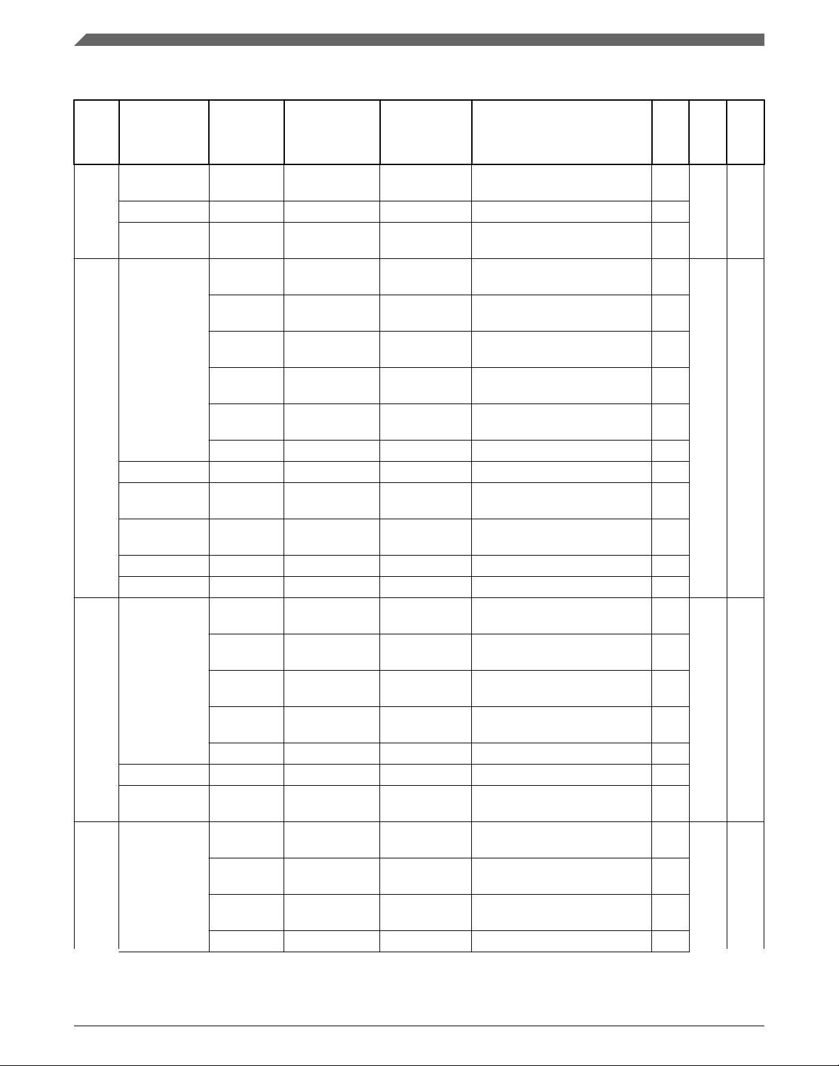
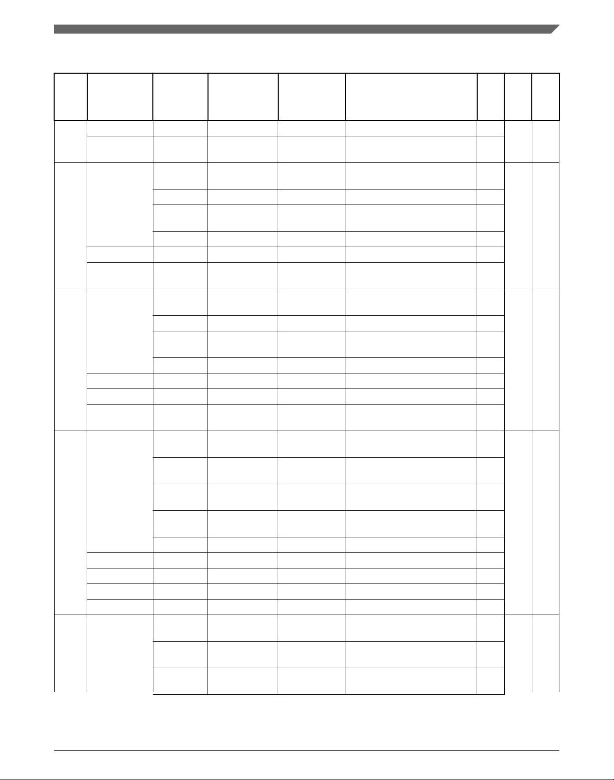
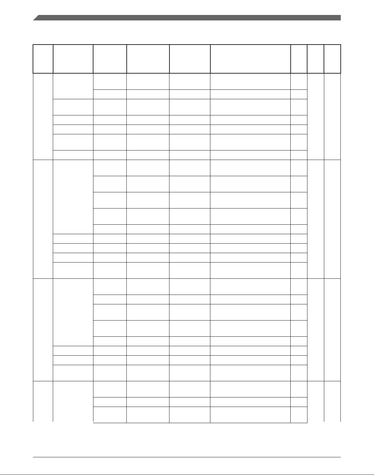
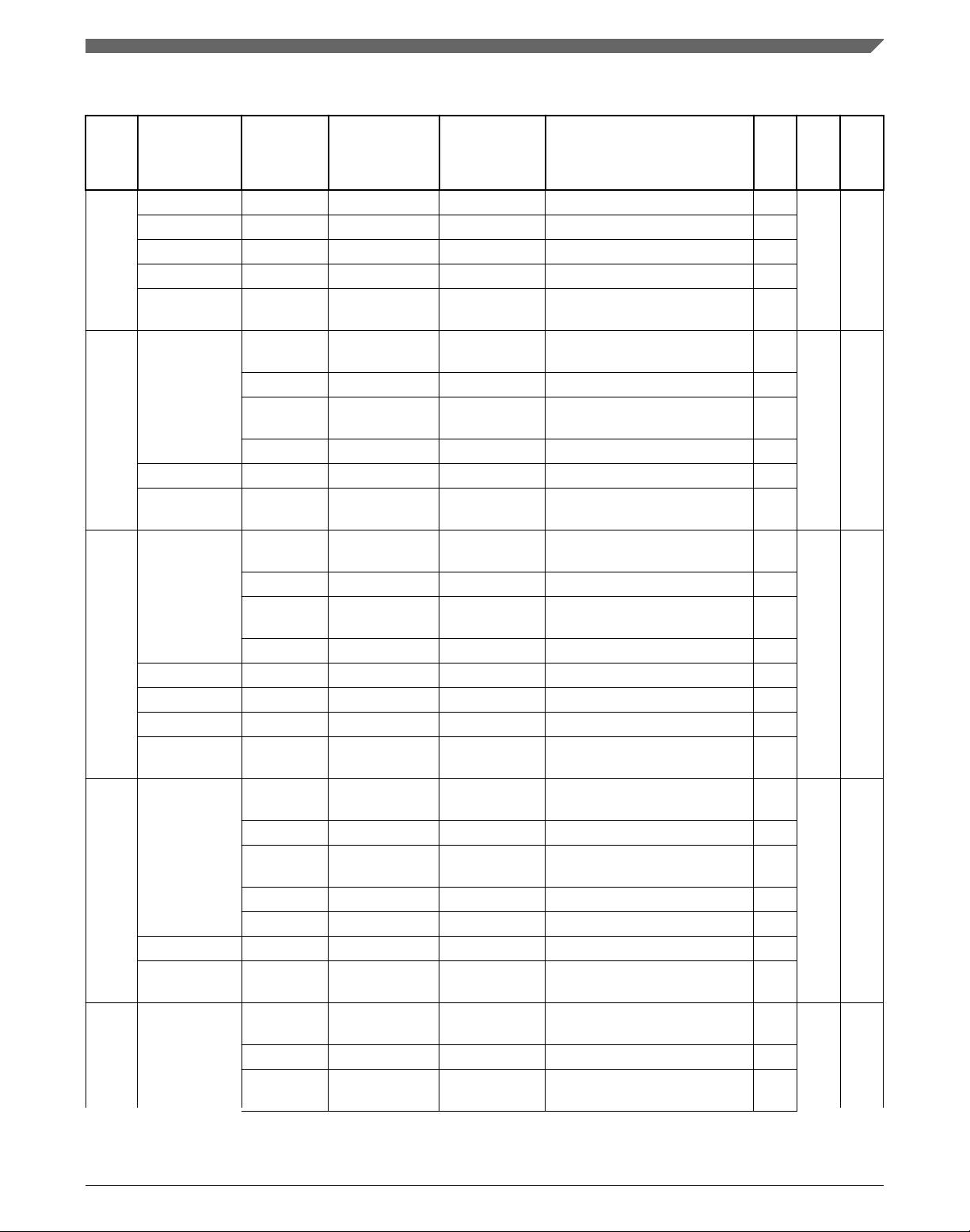
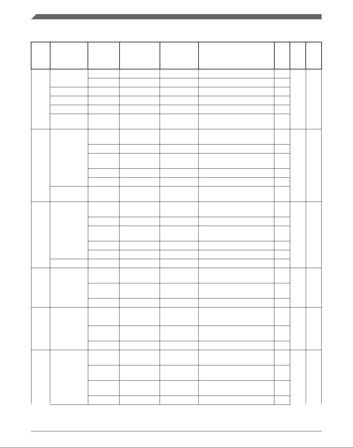
Table 8. Pin muxing (continued)
Port
Pin
SIUL2 MSCR/
IMCR
Number
MSCR/
IMCR SSS
Value
1
Signal Module Short Signal Description Dir
LQFP144
BGA257
IMCR[49] 0001 CS0 DSPI2 DSPI 2 Peripheral Chip Select
0
I
IMCR[98] 0001 B3 FlexPWM_0 FlexPWM_0 Channel B Input 3 I
IMCR[176] 0001 REQ3 SIUL2 SIUL2 External Interrupt
Source 3
I
A[4] MSCR[4] 0000
(Default)
GPIO[4] SIUL2-GPIO[4] General Purpose IO A[4] I/O 108 D16
0001 ETC0 eTimer_1 eTimer_1 Input/Output Data
Channel 0
I/O
0010 CS1 DSPI2 DSPI 2 Peripheral Chip Select
1
O
0011 ETC4 eTimer_0 eTimer_0 Input/Output Data
Channel 4
I/O
0100 A2 FlexPWM_1 FlexPWM_1 Channel A Input/
Output 2
I/O
0101-1111 — Reserved — —
IMCR[112] 0001 A2 FlexPWM_1 FlexPWM_1 Channel A Input 2 I
IMCR[177] 0001 REQ4 SIUL2 SIUL2 External Interrupt
Source 4
I
IMCR[172] 0000
(Default)
FAB MC_RGM RGM Force Alternate Boot
Mode
I
IMCR[65] 0001 ETC0 eTimer_1 eTimer_1 Input Data Channel 0 I
IMCR[63] 0011 ETC4 eTimer_0 eTimer_0 Input Data Channel 4 I
A[5] MSCR[5] 0000
(Default)
GPIO[5] SIUL2-GPIO[5] General Purpose IO A[5] I/O 14 H4
0001 CS0 DSPI1 DSPI 1 Peripheral Chip Select
0
I/O
0010 ETC5 eTimer_1 eTimer_1 Input/Output Data
Channel 5
I/O
0011 CS7 DSPI0 DSPI 0 Peripheral Chip Select
7
O
0100-1111 — Reserved — —
IMCR[70] 0001 ETC5 eTimer_1 eTimer_1 Input Data Channel 5 I
IMCR[178] 0001 REQ5 SIUL2 SIUL2 External Interrupt
Source 5
I
A[6] MSCR[6] 0000
(Default)
GPIO[6] SIUL2-GPIO[6] General Purpose IO A[6] I/O 2 D1
0001 SCK DSPI1 DSPI 1 Input/Output Serial
Clock
I/O
0010 ETC2 eTimer_2 eTimer_2 Input/Output Data
Channel 2
I/O
0011-1111 — Reserved — —
Table continues on the next page...
Pinouts
MPC5744P Data Sheet, Rev. 6.1, 11/2017
16 NXP Semiconductors
剩余114页未读,继续阅读
277 浏览量
121 浏览量
464 浏览量
370 浏览量
111 浏览量

我们一起摸爬叉
- 粉丝: 34
- 资源: 3
 我的内容管理
展开
我的内容管理
展开


最新资源
- jackal:al狼-通过浏览器观看直播电视
- E-chalak
- jQuery城市楼房动画特效.zip
- 志
- 薪酬分配制度实施要点
- Isconna.Python:Isconna算法的Python移植
- joiner:使用“go generate”命令的通用 strings.Join 实现
- 天星娱乐网祝福频道
- 2024年IDEA新手使用教程:详解,让你轻松上手!
- link_state_demo::rocket:演示如何在Apollo Link State中支持多个商店
- ASPICE PAM 31中英文对照版本.zip
- 企业银行系统解决方案
- javaweb
- gitlab安装包.zip
- SmartPack智能物流.zip
- epam-devops-m2:“ DevOps – BigData”(epam)主任务存储库
