没有合适的资源?快使用搜索试试~ 我知道了~
首页dsp6416开发手册
dsp6416开发手册
需积分: 36 38 下载量 21 浏览量
更新于2023-03-16
评论 2
收藏 2.06MB PDF 举报
dsp6416开发手册dsp6416开发手册dsp6416开发手册dsp6416开发手册dsp6416开发手册
资源详情
资源评论
资源推荐
TMS320C6414, TMS320C6415, TMS320C6416
FIXED-POINT DIGITAL SIGNAL PROCESSORS
SPRS146N − FEBRUARY 2001 − REVISED MAY 2005
1
POST OFFICE BOX 1443 • HOUSTON, TEXAS 77251−1443
Highest-Performance Fixed-Point Digital
Signal Processors (DSPs)
− 2-, 1.67-, 1.39-ns Instruction Cycle Time
− 500-, 600-, 720-MHz Clock Rate
− Eight 32-Bit Instructions/Cycle
− Twenty-Eight Operations/Cycle
− 4000, 4800, 5760 MIPS
− Fully Software-Compatible With C62x™
− C6414/15/16 Devices Pin-Compatible
VelociTI.2™ Extensions to VelociTI™
Advanced Very-Long-Instruction-Word
(VLIW) TMS320C64x™ DSP Core
− Eight Highly Independent Functional
Units With VelociTI.2™ Extensions:
− Six ALUs (32-/40-Bit), Each Supports
Single 32-Bit, Dual 16-Bit, or Quad
8-Bit Arithmetic per Clock Cycle
− Two Multipliers Support
Four 16 x 16-Bit Multiplies
(32-Bit Results) per Clock Cycle or
Eight 8 x 8-Bit Multiplies
(16-Bit Results) per Clock Cycle
− Non-Aligned Load-Store Architecture
− 64 32-Bit General-Purpose Registers
− Instruction Packing Reduces Code Size
− All Instructions Conditional
Instruction Set Features
− Byte-Addressable (8-/16-/32-/64-Bit Data)
− 8-Bit Overflow Protection
− Bit-Field Extract, Set, Clear
− Normalization, Saturation, Bit-Counting
− VelociTI.2™ Increased Orthogonality
Viterbi Decoder Coprocessor (VCP) [C6416]
− Supports Over 600 7.95-Kbps AMR
− Programmable Code Parameters
Turbo Decoder Coprocessor (TCP) [C6416]
− Supports up to 7 2-Mbps or
43 384-Kbps 3GPP (6 Iterations)
− Programmable Turbo Code and
Decoding Parameters
L1/L2 Memory Architecture
− 128K-Bit (16K-Byte) L1P Program Cache
(Direct Mapped)
− 128K-Bit (16K-Byte) L1D Data Cache
(2-Way Set-Associative)
− 8M-Bit (1024K-Byte) L2 Unified Mapped
RAM/Cache (Flexible Allocation)
Two External Memory Interfaces (EMIFs)
− One 64-Bit (EMIFA), One 16-Bit (EMIFB)
− Glueless Interface to Asynchronous
Memories (SRAM and EPROM) and
Synchronous Memories (SDRAM,
SBSRAM, ZBT SRAM, and FIFO)
− 1280M-Byte Total Addressable External
Memory Space
Enhanced Direct-Memory-Access (EDMA)
Controller (64 Independent Channels)
Host-Port Interface (HPI)
− User-Configurable Bus Width (32-/16-Bit)
32-Bit/33-MHz, 3.3-V PCI Master/Slave
Interface Conforms to PCI Specification 2.2
[C6415/C6416 ]
− Three PCI Bus Address Registers:
Prefetchable Memory
Non-Prefetchable Memory I/O
− Four-Wire Serial EEPROM Interface
− PCI Interrupt Request Under DSP
Program Control
− DSP Interrupt Via PCI I/O Cycle
Three Multichannel Buffered Serial Ports
− Direct I/F to T1/E1, MVIP, SCSA Framers
− Up to 256 Channels Each
− ST-Bus-Switching-, AC97-Compatible
− Serial Peripheral Interface (SPI)
Compatible (Motorola™)
Three 32-Bit General-Purpose Timers
Universal Test and Operations PHY
Interface for ATM (UTOPIA) [C6415/C6416]
− UTOPIA Level 2 Slave ATM Controller
− 8-Bit Transmit and Receive Operations
up to 50 MHz per Direction
− User-Defined Cell Format up to 64 Bytes
Sixteen General-Purpose I/O (GPIO) Pins
Flexible PLL Clock Generator
IEEE-1149.1 (JTAG
†
)
Boundary-Scan-Compatible
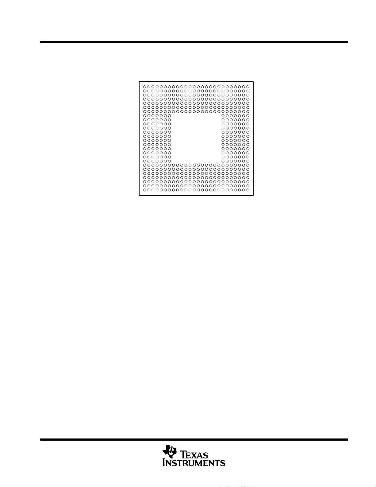
532-Pin Ball Grid Array (BGA) Package
(GLZ, ZLZ and CLZ Suffixes), 0.8-mm Ball
Pitch
0.13-µm/6-Level Cu Metal Process (CMOS)
3.3-V I/Os, 1.2-V/1.25-V Internal (500 MHz)
3.3-V I/Os, 1.4-V Internal (600 and 720 MHz)
Please be aware that an important notice concerning availability, standard warranty, and use in critical applications of
Texas Instruments semiconductor products and disclaimers thereto appears at the end of this data sheet.
PRODUCTION DATA information is current as of publication date.
Products conform to specifications per the terms of Texas Instruments
standard warranty. Production processing does not necessarily include
testing of all parameters.
Copyright © 2005 Texas Instruments Incorporated
C62x, VelociTI.2, VelociTI, and TMS320C64x are trademarks of Texas Instruments.
Motorola is a trademark of Motorola, Inc.
†
IEEE Standard 1149.1-1990 Standard-Test-Access Port and Boundary Scan Architecture.
TMS320C6414, TMS320C6415, TMS320C6416
FIXED-POINT DIGITAL SIGNAL PROCESSORS
SPRS146N − FEBRUARY 2001 − REVISED MAY 2005
2
POST OFFICE BOX 1443 • HOUSTON, TEXAS 77251−1443
Table of Contents
reset 75. . . . . . . . . . . . . . . . . . . . . . . . . . . . . . . . . . . . . . . . . . .
absolute maximum ratings over operating case
temperature range 76. . . . . . . . . . . . . . . . . . . . . . . . . .
recommended operating conditions 76. . . . . . . . . . . . . . . .
electrical characteristics over recommended ranges of
supply voltage and operating case temperature 77.
recommended clock and control signal transition
behavior 77. . . . . . . . . . . . . . . . . . . . . . . . . . . . . . . . . . .
parameter measurement information 78. . . . . . . . . . . . . . .
input and output clocks 80. . . . . . . . . . . . . . . . . . . . . . . . . . .
asynchronous memory timing 84. . . . . . . . . . . . . . . . . . . . .
programmable synchronous interface timing 88. . . . . . . .
synchronous DRAM timing 93. . . . . . . . . . . . . . . . . . . . . . . .
HOLD
/HOLDA timing 103. . . . . . . . . . . . . . . . . . . . . . . . . . .
BUSREQ timing 104. . . . . . . . . . . . . . . . . . . . . . . . . . . . . . . .
reset timing 105. . . . . . . . . . . . . . . . . . . . . . . . . . . . . . . . . . . .
external interrupt timing 107. . . . . . . . . . . . . . . . . . . . . . . . .
host-port interface (HPI) timing 108. . . . . . . . . . . . . . . . . . .
peripheral component interconnect (PCI) timing
[C6415 and C6416 only] 113. . . . . . . . . . . . . . . . . . . .
multichannel buffered serial port (McBSP) timing 116. . . .
UTOPIA slave timing [C6415 and C6416 only] 127. . . . . .
timer timing 130. . . . . . . . . . . . . . . . . . . . . . . . . . . . . . . . . . . .
general-purpose input/output (GPIO) port timing 131. . . .
JTAG test-port timing 132. . . . . . . . . . . . . . . . . . . . . . . . . . .
mechanical data 133. . . . . . . . . . . . . . . . . . . . . . . . . . . . . . . .
revision history 2. . . . . . . . . . . . . . . . . . . . . . . . . . . . . . . . . . . . . .
GLZ, ZLZ and CLZ BGA packages (bottom view) 3. . . . . . . .
description 4. . . . . . . . . . . . . . . . . . . . . . . . . . . . . . . . . . . . . . . . .
device characteristics 5. . . . . . . . . . . . . . . . . . . . . . . . . . . . . . . .
device compatibility 6. . . . . . . . . . . . . . . . . . . . . . . . . . . . . . . . . .
functional block and CPU (DSP core) diagram 7. . . . . . . . . . .
CPU (DSP core) description 8. . . . . . . . . . . . . . . . . . . . . . . . . .
memory map summary 11. . . . . . . . . . . . . . . . . . . . . . . . . . . . . .
peripheral register descriptions 14. . . . . . . . . . . . . . . . . . . . . . .
EDMA channel synchronization events 27. . . . . . . . . . . . . . . .
interrupt sources and interrupt selector 29. . . . . . . . . . . . . . . .
signal groups description 31. . . . . . . . . . . . . . . . . . . . . . . . . . . .
device configurations 36. . . . . . . . . . . . . . . . . . . . . . . . . . . . . . .
multiplexed pins 40. . . . . . . . . . . . . . . . . . . . . . . . . . . . . . . . . . . .
debugging considerations 40. . . . . . . . . . . . . . . . . . . . . . . . . . .
terminal functions 42. . . . . . . . . . . . . . . . . . . . . . . . . . . . . . . . . .
development support 62. . . . . . . . . . . . . . . . . . . . . . . . . . . . . . . .
device support 63. . . . . . . . . . . . . . . . . . . . . . . . . . . . . . . . . . . . .
clock PLL 66. . . . . . . . . . . . . . . . . . . . . . . . . . . . . . . . . . . . . . . . .
general-purpose input/output (GPIO) 69. . . . . . . . . . . . . . . . . .
power-down mode logic 70. . . . . . . . . . . . . . . . . . . . . . . . . . . . .
power-supply sequencing 72. . . . . . . . . . . . . . . . . . . . . . . . . . . .
power-supply decoupling 73. . . . . . . . . . . . . . . . . . . . . . . . . . . .
IEEE 1149.1 JTAG compatibility statement 74. . . . . . . . . . . . .
EMIF device speed 74. . . . . . . . . . . . . . . . . . . . . . . . . . . . . . . . .
bootmode 75. . . . . . . . . . . . . . . . . . . . . . . . . . . . . . . . . . . . . . . . .
REVISION HISTORY
This data sheet revision history highlights the technical changes made to the SPRS146M device-specific data
sheet to make it an SPRS146N revision.
Scope: Applicable updates to the C64x device family, specifically relating to the C6414, C6415, and C6416
devices, have been incorporated.
PAGE(S)
NO.
ADDITIONS/CHANGES/DELETIONS
Global:
Added “CLZ” (532-pin plastic BGA, Pb−free bump and Pb−free soldered balls) mechanical package information
TMS320C6414, TMS320C6415, TMS320C6416
FIXED-POINT DIGITAL SIGNAL PROCESSORS
SPRS146N − FEBRUARY 2001 − REVISED MAY 2005
3
POST OFFICE BOX 1443 • HOUSTON, TEXAS 77251−1443
GLZ, ZLZ and CLZ BGA packages (bottom view)
GLZ, ZLZ and CLZ 532-PIN BALL GRID ARRAY (BGA) PACKAGE
( BOTTOM VIEW)
†
A
2
B
1 3
4
5
6
7
8
9
10
11
12
13
14
15
16
17
18
19
20
21
22
23
24
25
26
C
D
E
F
G
H
J
K
L
M
N
P
R
T
U
V
W
Y
AA
AB
AC
AD
AE
AF
†
The ZLZ mechanical package designator represents the version of the GLZ package with lead-free soldered balls. For more detailed
information, see the Mechanical Data section of this document.
†
The CLZ mechanical package designator represents the version of the GLZ package with lead-free bump and lead−free soldered balls.
For more detailed information, see the Mechanical Data section of this document.
TMS320C6414, TMS320C6415, TMS320C6416
FIXED-POINT DIGITAL SIGNAL PROCESSORS
SPRS146N − FEBRUARY 2001 − REVISED MAY 2005
4
POST OFFICE BOX 1443 • HOUSTON, TEXAS 77251−1443
description
The TMS320C64x™ DSPs (including the TMS320C6414, TMS320C6415, and TMS320C6416 devices) are the
highest-performance fixed-point DSP generation in the TMS320C6000™ DSP platform. The TMS320C64x™
(C64x™
†
) device is based on the second-generation high-performance, advanced VelociTI™
very-long-instruction-word (VLIW) architecture (VelociTI.2™) developed by Texas Instruments (TI), making
these DSPs an excellent choice for multichannel and multifunction applications. The C64x™ is a
code-compatible member of the C6000™ DSP platform.
With performance of up to 5760 million instructions per second (MIPS) at a clock rate of 720 MHz, the C64x
devices offer cost-effective solutions to high-performance DSP programming challenges. The C64x DSPs
possess the operational flexibility of high-speed controllers and the numerical capability of array processors.
The C64x™ DSP core processor has 64 general-purpose registers of 32-bit word length and eight highly
independent functional units—two multipliers for a 32-bit result and six arithmetic logic units (ALUs)— with
VelociTI.2™ extensions. The VelociTI.2™ extensions in the eight functional units include new instructions to
accelerate the performance in key applications and extend the parallelism of the VelociTI™ architecture. The
C64x can produce four 16-bit multiply-accumulates (MACs) per cycle for a total of 2880 million MACs per
second (MMACS), or eight 8-bit MACs per cycle for a total of 5760 MMACS. The C64x DSP also has
application-specific hardware logic, on-chip memory, and additional on-chip peripherals similar to the other
C6000™ DSP platform devices.
The C6416 device has two high-performance embedded coprocessors [Viterbi Decoder Coprocessor (VCP)
and Turbo Decoder Coprocessor (TCP)] that significantly speed up channel-decoding operations on-chip. The
VCP operating at CPU clock divided-by-4 can decode over 600 7.95-Kbps adaptive multi-rate (AMR) [K = 9,
R = 1/3] voice channels. The VCP supports constraint lengths K = 5, 6, 7, 8, and 9, rates R = 1/2, 1/3, and 1/4,
and flexible polynomials, while generating hard decisions or soft decisions. The TCP operating at CPU clock
divided-by-2 can decode up to forty-three 384-Kbps or seven 2-Mbps turbo encoded channels (assuming 6
iterations). The TCP implements the max*log-map algorithm and is designed to support all polynomials and
rates required by Third-Generation Partnership Projects (3GPP and 3GPP2), with fully programmable frame
length and turbo interleaver. Decoding parameters such as the number of iterations and stopping criteria are
also programmable. Communications between the VCP/TCP and the CPU are carried out through the EDMA
controller.
The C64x uses a two-level cache-based architecture and has a powerful and diverse set of peripherals. The
Level 1 program cache (L1P) is a 128-Kbit direct mapped cache and the Level 1 data cache (L1D) is a 128-Kbit
2-way set-associative cache. The Level 2 memory/cache (L2) consists of an 8-Mbit memory space that is
shared between program and data space. L2 memory can be configured as mapped memory or combinations
of cache (up to 256K bytes) and mapped memory. The peripheral set includes three multichannel buffered serial
ports (McBSPs); an 8-bit Universal Test and Operations PHY Interface for Asynchronous Transfer Mode (ATM)
Slave [UTOPIA Slave] port (C6415/C6416 only); three 32-bit general-purpose timers; a user-configurable 16-bit
or 32-bit host-port interface (HPI16/HPI32); a peripheral component interconnect (PCI) [C6415/C6416 only];
a general-purpose input/output port (GPIO) with 16 GPIO pins; and two glueless external memory interfaces
(64-bit EMIFA and 16-bit EMIFB
‡
), both of which are capable of interfacing to synchronous and asynchronous
memories and peripherals.
The C64x has a complete set of development tools which includes: an advanced C compiler with C64x-specific
enhancements, an assembly optimizer to simplify programming and scheduling, and a Windows™ debugger
interface for visibility into source code execution.
TMS320C6000, C64x, and C6000 are trademarks of Texas Instruments.
Windows is a registered trademark of the Microsoft Corporation.
All trademarks are the property of their respective owners.
†
Throughout the remainder of this document, the TMS320C6414, TMS320C6415, and TMS320C6416 shall be referred to as TMS320C64x or
C64x where generic, and where specific, their individual full device part numbers will be used or abbreviated as C6414, C6415, or C6416.
‡
These C64x™ devices have two EMIFs (64-bit EMIFA and 16-bit EMIFB). The prefix “A” in front of a signal name indicates it is an EMIFA signal
whereas a prefix “B” in front of a signal name indicates it is an EMIFB signal. Throughout the rest of this document, in generic EMIF areas of
discussion, the prefix “A” or “B” may be omitted from the signal name.
TMS320C6414, TMS320C6415, TMS320C6416
FIXED-POINT DIGITAL SIGNAL PROCESSORS
SPRS146N − FEBRUARY 2001 − REVISED MAY 2005
5
POST OFFICE BOX 1443 • HOUSTON, TEXAS 77251−1443
device characteristics
Table 1 provides an overview of the C6414, C6415, and C6416 DSPs. The table shows significant features of
the C64x devices, including the capacity of on-chip RAM, the peripherals, the CPU frequency, and the package
type with pin count.
Table 1. Characteristics of the C6414, C6415, and C6416 Processors
HARDWARE FEATURES C6414, C6415, AND C6416
EMIFA (64-bit bus width)
(default clock source = AECLKIN)
1
Peripherals
EMIFB (16-bit bus width)
(default clock source = BECLKIN)
1
Not all peripherals pins
are available at the
EDMA (64 independent channels) 1
are available at the
same time. (For more
HPI (32- or 16-bit user selectable) 1 (HPI16 or HPI32)
same time
.
(For more
details, see the Device
PCI (32-bit) [DeviceID Register value 0xA106] 1 [C6415/C6416 only]
details, see the Device
Configuration section.)
Peripheral performance
McBSPs (default internal clock source =
CPU/4 clock frequency)
3
Peripheral performance
is de
p
endent on
UTOPIA (8-bit mode) 1 [C6415/C6416 only]
is dependent on
chip-level configuration.
32-Bit Timers (default internal clock source =
CPU/8 clock frequency)
3
General-Purpose Input/Output 0 (GP0) 16
Decoder Coprocessors
VCP 1 (C6416 only)
Decoder Coprocessors
TCP 1 (C6416 only)
Size (Bytes) 1056K
On-Chip Memory
Organization
16K-Byte (16KB) L1 Program (L1P) Cache
16KB L1 Data (L1D) Cache
1024KB Unified Mapped RAM/Cache (L2)
CPU ID + CPU Rev ID Control Status Register (CSR.[31:16]) 0x0C01
Device_ID
Silicon Revision Identification Register
(DEVICE_REV [19:16])
Address: 0x01B0 0200
DEVICE_REV[19:16] Silicon Revision
1111 1.03 or earlier
0001 1.03
0010 or 0000 1.1
0011 2.0
Frequency MHz 500, 600, 720
Cycle Time ns
2 ns (C6414-5E0, C6415-5E0, C6416-5E0) and
(C6414A-5E0, C6415A-5E0, C6416A-5E0)
[500-MHz CPU, 100-MHz EMIF]
†
1.67 ns (C6414-6E3, C6415-6E3, C6416-6E3) and
(C6414A-6E3, C6415A-6E3, C6416A-6E3)
[600-MHz CPU, 133-MHz EMIFA]
†
1.39 ns (C6414-7E3, C6415-7E3, C6416-7E3)
[720-MHz CPU, 133-MHz EMIFA]
†
Voltage
Core (V)
1.2 V (-5E0)
1.25 V (A-5E0)
1.4 V (-6E3, A-6E3, -7E3)
I/O (V) 3.3 V
PLL Options CLKIN frequency multiplier Bypass (x1), x6, x12
BGA Package 23 x 23 mm 532-Pin BGA (GLZ, ZLZ and CLZ)
Process Technology µm 0.13 µm
Product Status
Product Preview (PP), Advance Information
(AI), Production Data (PD)
PD
‡
†
On these C64x™ devices, the rated EMIF speed affects only the SDRAM interface on EMIFA. For more detailed information, see the EMIF
Device Speed section of this data sheet.
‡
All devices are now at the Production Data (PD) stage of development.
剩余142页未读,继续阅读
weixin_43010280
- 粉丝: 0
- 资源: 3
上传资源 快速赚钱
- 我的内容管理 收起
- 我的资源 快来上传第一个资源
- 我的收益 登录查看自己的收益
- 我的积分 登录查看自己的积分
- 我的C币 登录后查看C币余额
- 我的收藏
- 我的下载
- 下载帮助
会员权益专享
最新资源
- c++校园超市商品信息管理系统课程设计说明书(含源代码) (2).pdf
- 建筑供配电系统相关课件.pptx
- 企业管理规章制度及管理模式.doc
- vb打开摄像头.doc
- 云计算-可信计算中认证协议改进方案.pdf
- [详细完整版]单片机编程4.ppt
- c语言常用算法.pdf
- c++经典程序代码大全.pdf
- 单片机数字时钟资料.doc
- 11项目管理前沿1.0.pptx
- 基于ssm的“魅力”繁峙宣传网站的设计与实现论文.doc
- 智慧交通综合解决方案.pptx
- 建筑防潮设计-PowerPointPresentati.pptx
- SPC统计过程控制程序.pptx
- SPC统计方法基础知识.pptx
- MW全能培训汽轮机调节保安系统PPT教学课件.pptx
资源上传下载、课程学习等过程中有任何疑问或建议,欢迎提出宝贵意见哦~我们会及时处理!
点击此处反馈
安全验证
文档复制为VIP权益,开通VIP直接复制
信息提交成功
评论0