没有合适的资源?快使用搜索试试~ 我知道了~
首页博世KWP2000英文原版
博世KWP2000英文原版
需积分: 24 173 浏览量
更新于2023-05-25
评论
收藏 643KB PDF 举报
Y445 S00 728-V42 Confidential Keyword Protocol 2000
资源详情
资源评论
资源推荐

P_532
DS-CV/EET
Y445 S00 728-V42 Confidential
Keyword Protocol 2000
KW2000 - 1791 -
ComVar - kw2000
21.10.2005 kwp2000_overview.fm
© Robert Bosch GmbH reserves all rights even in the event of industrial property rights. We reserve all rights of disposal such as copying and passing on to third parties.
14 Keyword Protocol 2000 (KW2000)
Function group: Keyword-Protocol 2000
KWP2000
Overview of the component The main purpose of diagnostic software is to retrieve diagnostic information from the ECU to the external
tester equipment. Currently, the physical media ETK emulation memory interface, CAN and K-line can be
serviced, but future extensions are possible. The software fulfils the concerning diagnostic and emission
related system systems for road vehicles according to the ISO, CARB and SAE specifications.
Besides the application of diagnosis the communication software is als used for:
• Programming software aund data into flash memory devices
• End of line programming
• OnBoard-Diagnosis using functional addressing for emission related ECUs
• Factory tests to verify the functionality of all hardware devices
• Remote Control for simulation and software test which is useful during the software development stage
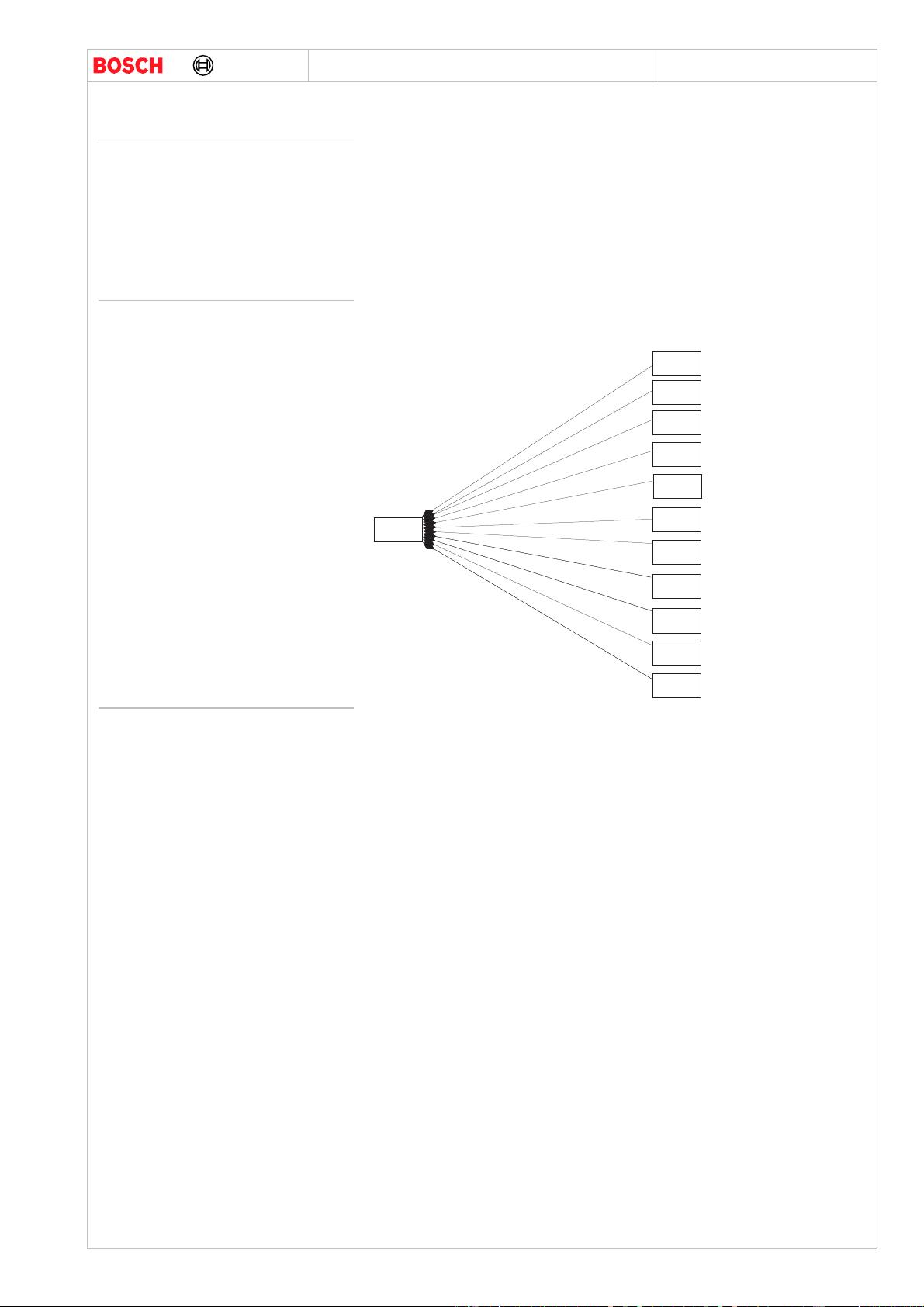
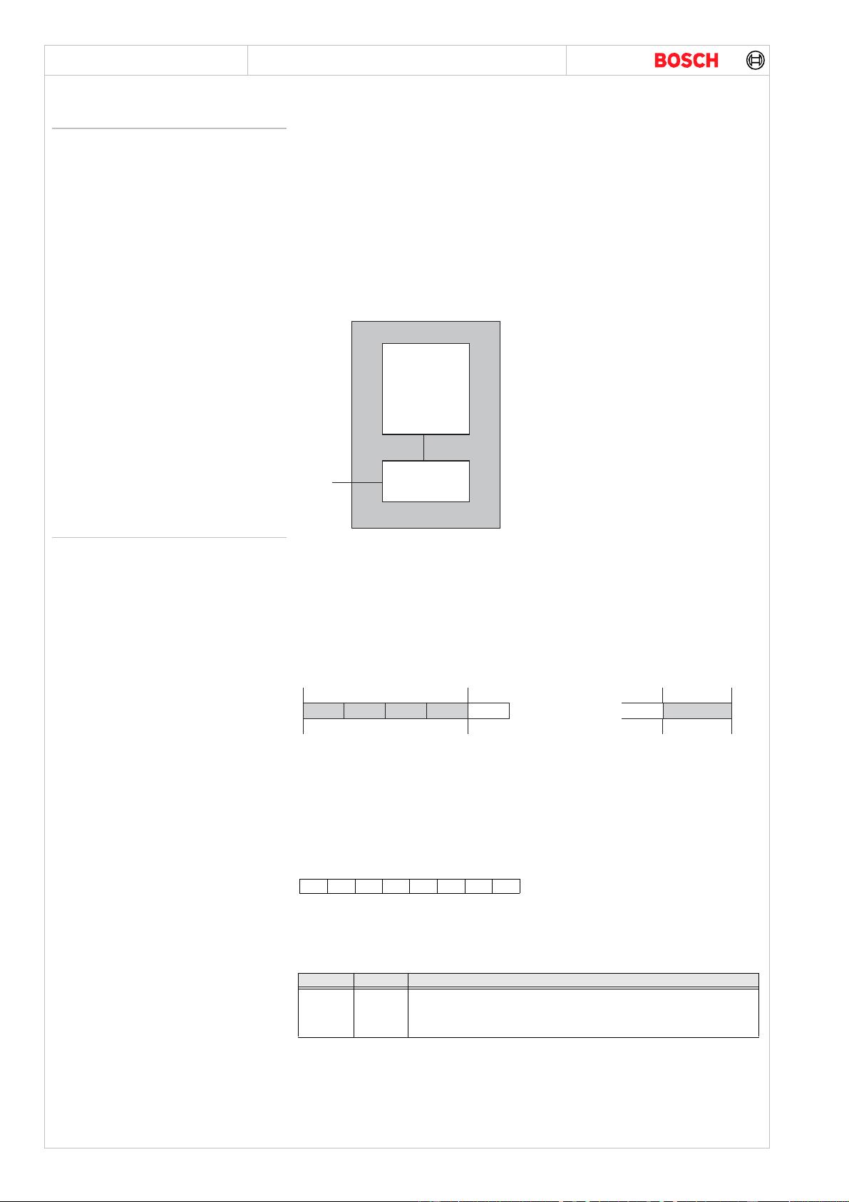
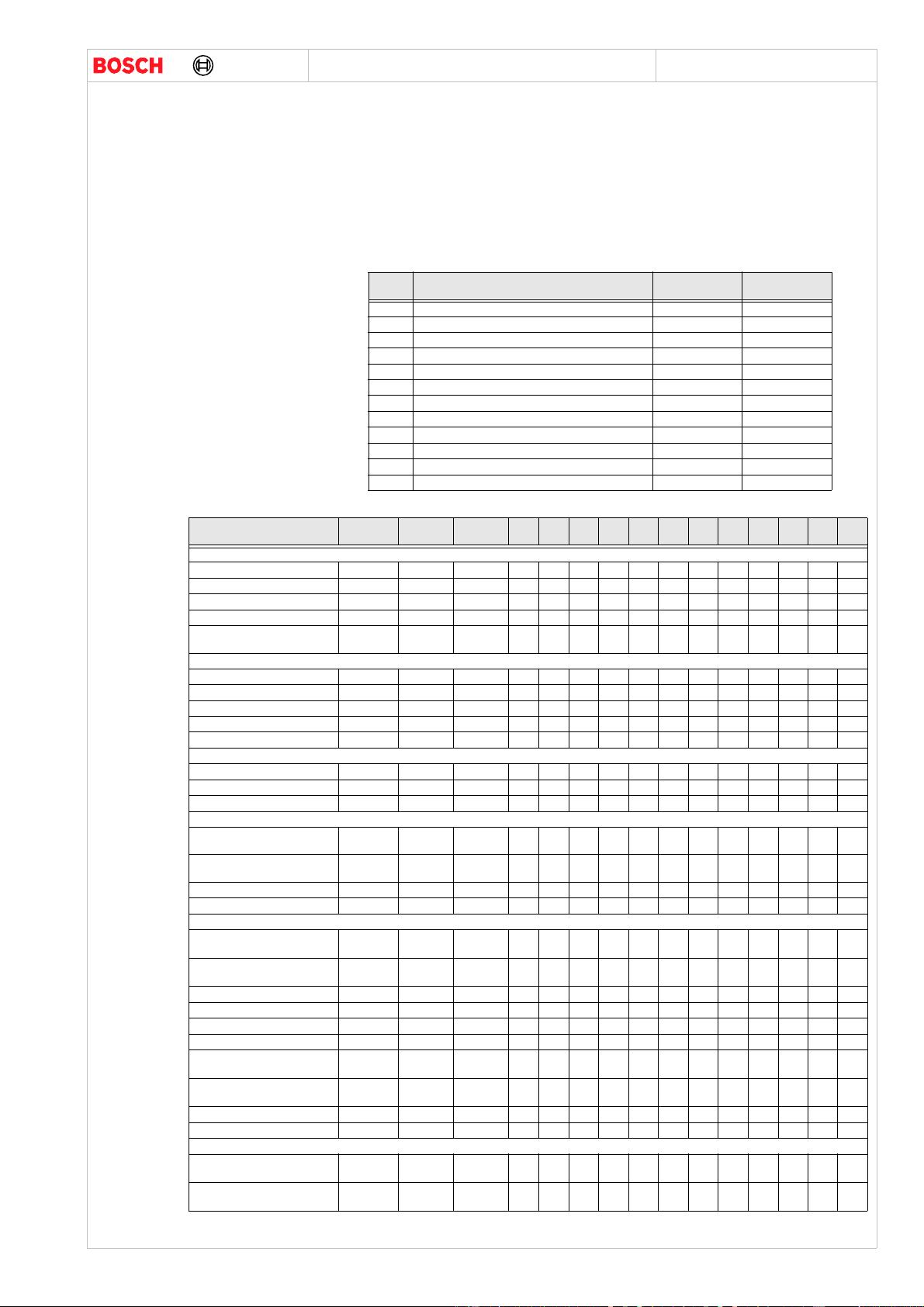
Structure of the component The kw2000 component consists the project specific services in subcomponent.
Figure 1624 : Subcomponents of project specific kw2000 services
Subfunctions
See “Keyword Protocol 2000 Implementation (kwp2000)” on page 1792.
See “KWP 2000 diagnosis on CAN implementation (DiagOnCAN)” on page 1801.
See “Keyword protocol 2000 flash programming (kwp2000_flash)” on page 1804.
See “startCommunication SID $81 (K2STC)” on page 1862.
See “stopCommunication SID $82 (K2SPC)” on page 1863.
See “accessTimingParameters SID $83 (K2ATP)” on page 1864.
See “ReadEcuIdentification SID $1A (K2REI)” on page 1819.
See “startDiagnosticSession SID $10 (K2STDS)” on page 1810.
See “testerPresent SID $3E (K2TP)” on page 1858.
See “ecuReset SID $11 (K2ER)” on page 1812.
See “securityAccess SID $27 (K2SECA)” on page 1829.
See “Reading ECU data (ReadDataByLocalIdentifier SID $21) (K2RDLI)” on page 1822.
See “writeDataByLocalIdentifier service SID $3B (K2WRDLI)” on page 1855.
See “dynamicallyDefineLocalIdentifier SID $2C (K2DDLI)” on page 1834.
See “readDiagnosticTroubleCodesByStatus SID $18 (K2RDTCBS)” on page 1817.
See “ReadStatusOfDiagnosticTroubleCodes SID $17 (K2RSODTC)” on page 1815.
See “ClearDiagnosticInformation SID $14 (K2CDI)” on page 1814.
See “readMemoryByAddress SID $23 (K2RMBA)” on page 1828.
See “requestRoutineResultsByLocalIdentifier SID 33 (K2RRRBLI)” on page 1849.
See “startRoutineByLocalIdentifier SID 31h (K2STRBLI)” on page 1844.
See “stopRoutineByLocalId (SID 32h) (K2SPRBLI)” on page 1847.
See “escapeCode (SID 80) (K2ESC)” on page 1859.
See “Write memory by address (SID 3D) (K2WMBA)” on page 1857.
See “Input/output control (InputOutputControlByLocalId SID $30) (K2IOCBLI)” on page 1836.
See “Request download (SID 34) (K2RQDN)” on page 1851.
See “Request upload (SID 35) (K2RQUP)” on page 1852.
See “Transfer data (SID 36) (K2TD)” on page 1853.
See “Request transfer exit (SID 37) (K2RTE)” on page 1854.
See “Communication Control SID $28 (ISO14229_CC)” on page 1831.
k w 2 0 0 0
k 2 c v l i b
k 2 s r b l i
k 2 s e c a
k 2 e s c
k 2 r r r b l i
k 2 r e i
k 2 r s o d t c
k 2 s p r b l i
k 2 c d i
k 2 r d t c b s
k 2 c c

- 1792 - kwp2000
ComVar - kwp2000
Y445 S00 728-V42 Confidential
Keyword Protocol 2000 Implementation
P_532
DS-CV/EET
kwp2000.fm 21.10.2005
© Robert Bosch GmbH reserves all rights even in the event of industrial property rights. We reserve all rights of disposal such as copying and passing on to third parties.
Keyword Protocol 2000 Implementation (kwp2000)
Function group: kwp2000
CARTRONIC-Structure:
ComVar -kwp2000
Functional overview The external communication software is made up of two parts:
• Communication handler
• Command Interpreter
The tasks of the communications handler are:
• Reaction to the stimulation of the diagnostic tester
• Establishing the operational mode (initialization with 5 Baud or Wakeup pattern)
• Realization of the connection with the corresponding operational mode
• Data transfer with the given timing
The tasks of the command interpreter are:
• Interpretation and execution of the received request blocks
• Information exchange with system components (inside the ECU)
• Creation of the corresponding response blocks
Figure 1625 : Overview of Keyword 2000 software structure
Functional description
Message structure A message consists of the following parts:
• Header
•Data Bytes
• Checksum
A byte in the message structure consists of:
• 1 Start bit
• 8 Data bits beginning with LSB
•1 Stop bit
Figure 1626 : Keyword 2000 message format
(1) Bytes are optional, depending on the format byte.
(2) Service Identification, part of data bytes.
Header The header consists of maximum 4 bytes. A format byte includes information about the form of the message.
Target and source address bytes are optional for use with multi node connections. An optional separate
length byte allows a message length up to 255 bytes. The different possibilities of using header bytes is
shown in the figure below.
Format byte - Fmt The format byte consists of 2 bits of address information and 6 bits of length information. The tester is
informed about use of header bytes by the key bytes in the startCommunication positive response message.
Table 1009: Format byte
A1, A0 define the form of the header which will be used by the message (see below). L5 .. L0 define the length
of a message from the beginning of the data field (service identification byte included) to the checksum byte
(not included). A message length of 1 to 63 bytes is possible. If L0 to L5 = 0, then the additional length byte
is included.
Table 1010: Header format definition
Target address byte - Tgt This is the target address for the message and is always used together with the source address byte.
According to SAE J2178-Part 1 (where the range of numbers 10h to 17h is assigned to "Engine Controllers"),
the physical address of EDC16C8 is 10h. The target address byte is optional and only necessary on multi
node bus topologies. For node-to-node connections it may be omitted.
C o m m a n d
I n t e r p r e t e r
C o m m u n i c a t i o n
H a n d l e r
K L i n e
k w
p
2 0 0 0
_
0 . d s f
H e a d e r D a t a b y t e s C h e c k s u m
F m t T g t S r c L e n
1
S I d
2
. . D a t a . . C S
m a x . 4 b y t e s m a x . 2 5 5 b y t e 1 b y t e
1
1
A1 A0 L5 L4 L3 L2 L1 L0
A1 A0 Mode
0
0
1
1
0
1
0
1
no address information
exception mode (CARB)
with address information, physical addressing
with address information, functional addressing

P_532
DS-CV/EET
Y445 S00 728-V42 Confidential
Keyword Protocol 2000 Implementation
kwp2000 - 1793 -
ComVar - kwp2000
21.10.2005 kwp2000.fm
© Robert Bosch GmbH reserves all rights even in the event of industrial property rights. We reserve all rights of disposal such as copying and passing on to third parties.
Source address byte - Src This is the address of the transmitting device. It must be a physical address. There are the same possibilities
for the values as described for physical target address bytes. Addresses for the tester are listed in SAE J2178
Part 1. This byte is optional (always used together whith target address byte) and only necessary on multi
node bus topologies. For node-to-node connections it may be omitted.
Table 1011: Target and Source address bytes
Length Byte - Len This byte is provided if the length in the header byte (L0 to L5) is set to zero. It allows the unit to transmit
messages with data fields longer than 63 bytes. With shorter messages it may be omitted. This byte defines
the length of a message from the beginning of the data field (service Id included) to the checksum byte (not
included). A data length of 1 to 255 bytes is possible. The longest message consists of a maximum of 260
bytes (4 bytes header, 255 bytes data and 1 byte checksum).
Data Bytes The data field may contain up to 63 or up to 255 bytes of information, depending on the use of length
information. The first byte of the data field is the service Identification byte. It may be followed by parameters
and data depending on the selected service.
Table 1012: Data byte information
Checksum Checksum is calculated by adding all the bytes excluding the Checksum. The final checksum is Modulo 256,
i.e low byte of the sum.
For example:
If a message consists of
<1> <2> <3> ...... <N>, <CS>
where <i> (1<i<N) corresponds to the numerical value of the ith byte.
<CS> = <CS>N
<CS>i (i = 2 to N) is defined as:
<CS>i = ( <CS>i-1 + <i>) Modulo 256 with <CS>1 = <1>
Types of Initialisation
5 Baud Initialisation The general form of a 5 baud initialisation is shown below. A 5 baud address-byte is transfered from the
tester. After sending the 5 baud address byte the tester will maintain the K-line on high level. After receiving
the 5 baud address byte the ECU will transmit the synchronisation pattern 55h and the two key bytes with the
actual communication baud rate. The tester transmits key byte 2 (inverse), then the ECU transmits the
address byte (inverse).
Figure 1627 : 5 Baud Initialisation
Table 1013: Timing values for 5 baud initialisation
These are fixed values. They cannot be changed by the accessTimingParameter service. Key bytes as
definded above. Baud rates from 1200 to 10400 baud are allowed for communication. The tester will
recognise the baud rate from the synchronistion byte (55h).
Fast Initialisation This is a point to point initialisation method. Only the addressed ECUs respond to the Start Communication
Request. So a bus arbitration mechanism is not required. It is possible to initialise more than one ECU on
the K-Line without having to break communication with the already initialised ECU. This means to say that
the Fast initialisation pattern directed at other ECUs will be ignored by the already initialised ECU.
The fast initialisation pattern should always be followed by a startCommunication service. The initialization is
said to be complete after the ECU sends the positive response to this service.
Byte Tester -> ECU ECU -> Tester
Target address ECU address (0x10) Tester address (0xXX)
Source address Tester address (0xXX) ECU address (0x10)
Description
SId Service Identification byte
Data Data bytes max. 254
Timing
Parameter
min. /
ms
max. /
ms
Desciptioin
W1 60 300 Time from end of the address byte to start of synchronisation pattern
W2 5 20 Time from end of the synchronisation pattern to the start of key byte 1
W3 0 20 Time between key byte 1 and key byte 2
W4 25 50 Time between key byte 2 (from ECU) and its inversion from the tester. Also the
time from the inverted key byte 2 from the tester and the inverted address from the
ECU
W5 300 - Time before the tester starts to transmit the address byte
A d d r e s s W o r d
" $ 5 5 " K B 1 K B 2
A d d r e s s
K B 2
5 B a u d
C o m m u n i c a t i o n B a u d r a t e
W 1
W 2
W 3
W 4
W 4
W 5
S t a r t
C o m m u n i c a t i o n
S t a r t C o m m u n i c a t i o n
P
2
P o s i t i v e R e s p o n s e
T e s t e r
E C U
P
3
I n i t i a l i z a t i o n
K W P 2 0 0 0 _ 5 . d s f A

- 1794 - kwp2000
ComVar - kwp2000
Y445 S00 728-V42 Confidential
Keyword Protocol 2000 Implementation
P_532
DS-CV/EET
kwp2000.fm 21.10.2005
© Robert Bosch GmbH reserves all rights even in the event of industrial property rights. We reserve all rights of disposal such as copying and passing on to third parties.
Figure 1628 : Fast Initialisation Timing Diagram
Parameters
Address and Keybytes
Table 1014: Address and Keybytes
Timing During normal operation the following timing parameters are relevant:
Figure 1629 : Message flow timing
Table 1015: Timing Parameters
Table 1016: Extended Timing Parameter Set
Table 1017: Timing Parameter for Fast Initialisation
Diagnostic Modes Each keyword protocol 2000 service supported to perform serial communication is assigned to one or
(usually) more diagnostic modes. Diagnostic modes are provided to establish different access levels to
keyword protocol 2000 functions for different users/testers ("multi-level security access"). For example the
manufacturer may have access to programming functions and therefore has to enter the diagnostic mode
"ECUProgrammingMode"; a repair shop may have access to some read and adjustment functions, for which
starting the diagnostic session "ECUAdjustmentMode" is required. To enter a diagnostic mode a
startDiagnosticSession request has to be performed.
After start of communication the "defaultMode-StandardDiagnosticMode", which contains all services
necessary to maintain communication, is active. These services are always available and are not access
protected. However, a securityAccess service (using the seed & key procedure) has to be performed before
entering a different diagnostic mode.
K W P 2 0 0 0 _ 3 . d s f
S t a r t C o m m u n i c a t i o n
s e r v i c e r e q u e s t
T
I n i L
W A K E U P P A T T E R N
T
W u p
P 2 o r R E Q / R E S P
P 3 o r I n t e r R E S P / R E Q
1 0 4 0 0 b a u d s
T
I d l e
N e w s e r v i c e
r e q u e s t
S t a r t C o m m u n i c a t i o n
s e r v i c e r e s p o n s e
T e s t e r
T e s t e rE C U
Type of Initialisation Address KeyByte 1 KeyByte 2
Fast Initialisation 0x10 0xDF 0x8F
Value Description
P1
P2
P3
P4
inter-byte-time in the ECU response message
Time between end of tester request and start of ECU response (inter-block-time)
Time between end of ECU response and start of new tester request (inter-block-time)
inter-byte-time in the tester request message
Timing
Parameter
min.
ms
default min.
ms
Resulution
ms/bit
default max.
ms
max.
ms
Resulution
ms/bit
P1
P2
P3
P4
0
0
0
0
0
0
0
0
---
0,5
0,5
0,5
20
1000
5000
20
20
Parameters Description ECU - Feature Remarks
min (ms) max (ms)
TIniL K-Line Low Time 24 26
TWup Time between Start of Low and Start
Communication request
49 51
Tidle K-Line idle time before new
initialisation
> 0 - This is the responsibility of the
Tester. The ECU is ready to
start communication as soon as
a break in communication is
detected.
T
i n i L
S t a r t C o m m u n i c a t i o n
T
W u P
T
I d l e
S t a r t C o m m u n i c a t i o n
P
2
P
3
S e r v i c e R e q u e s t
P o s i t i v e R e s p o n s e
T e s t e r
E C U
T e s t e r
E C U
S e r v i c e R e s p o n s e
P
2
P
P 4
P 1
I n t e r b y t e t i m e
T e s t e r
E C U
3
I n i t i a l i z a t i o n
P 4
I n t e r b y t e t i m e
T e s t e r
K W P 2 0 0 0 _ 4 . d s f A

P_532
DS-CV/EET
Y445 S00 728-V42 Confidential
Keyword Protocol 2000 Implementation
kwp2000 - 1795 -
ComVar - kwp2000
21.10.2005 kwp2000.fm
© Robert Bosch GmbH reserves all rights even in the event of industrial property rights. We reserve all rights of disposal such as copying and passing on to third parties.
In other words, any keyword protocol 2000 service (unless defaultMode-StandardDiagnosticMode services)
is not available, until a securityAccess service has been carried out and an appropriate diagnostic mode has
been entered. With EDC the vehicle manufacturer is free to assign any keyword protocol 2000 service to any
diagnostic mode (in a wise manner), even to the "unprotected" defaultMode-StandardDiagnosticMode, but
(as an exception) not to the ECUProgrammingMode: The services required for programming (eraseFlash,
writeFlash and compareChecksum) have to be assigned to the ECUProgrammingMode only. Note that
endOfLineSystemSupplierMode and systemSupplierSpecificMode are reserved for the system supplier.
Following diagnostic modes can be supported by EDC, however the number of diagnostic modes is limited
to 32.
Overview of Services
Table 1018: Supported Diagnostic Modes
Table 1019: List of Services Implemented (SIVS - Table) with diagnostic mode
DM
[Hex]
diagnosticMode (DM) Security access
required?
Security access
Mode [hex]
81 defaultMode NO
82 endOfLineUploadMode YES 0x01 / 0x02
83 endOfLineDownloadMode YES 0x03 / 0x04
85 ECUProgrammingMode YES 0x07 / 0x08
86 ECUDevelopmentMode YES 0x09 / 0x0A
87 ECUAdjustmentMode YES 0x0B / 0x0C
88 EOL VehicleUploadMode YES 0x11 / 0x12
89 EOL VehicleDownloadMode YES 0x13 / 0x14
90 EOL VehicleCustomerServiceUploadMode YES 0x15 / 0x16
91 EOL VehicleCustomerServiceDownloadMode YES 0x17 / 0x18
92 EOL EndCustomerServiceUoloadMode YES 0x19 / 0x1A
93 EOL EndCustomerServiceDownloadMode YES 0x1B / 0x1C
Diagnostic Service Name Mnemonic Request
[Hex]
Response
[Hex]
DM
81
DM
82
DM
83
DM
85
DM
86
DM
87
DM
88
DB
89
DM
90
DM
91
DM
92
DM
93
Communication services
startCommunication STC 81 C1 XXXXXXXXXXXX
stopCommunication SPC 82 C2 XXXXXXXXXXXX
accessTimingParamerters ATP 83 C3 XXXXXXXXXXXX
CommunicationControl CC 28 68 X X X
Control Diagnostic Trouble
Codes Setting
CDTCS 85 C5 X X X
Diagnostic management
startDiagnosticSession STDS 10 50 XXXXXXXXXXXX
securityAccess SECA 27 67 X XXXX XXXXXXX
testerPresent TP 3E 7E XXXXXXXXXXXX
readEcuIdentification REI 1A 5A XXXXXXXXXXXX
ecuReset ER 11 51 XXXXXXXXXXXX
Measuring
readDataByLocalIdentifier RDLI 21 61 XR XR XR
readMemoryByAddress RMEM 23 63 XR XR XR
dynamicallyDefineLocalIdentifier DDLI 2C - F0 6C - F0 XR XR XR
Fault memory
readStatusOfDiagnosticTrouble
Codes
RSODTC 17 57 XXX
readDiagnosticTroubleCodesBy
Status
RDTCBS 18 58 XXX
clearDiagnosticInformation CDI 14 54 XXX
readFreezeFrameData RFFD 12 52 XXXXXXXXXXXX
Flash Memory Programming
startRoutineByLocalIdentifier
(erase Flash)
STRBLI 31 - 02 71 - 02 X
requestRoutineResultsByLocal-
Identifier (erase Flash)
RRRBLI 33 - 02 73 - 02 X
requestUpload (read Flash) RQUP 35 75 XXXX
requestDownload (write Flash) RQDN 34 74 X X XXX
transferData TD 36 76 XXX XXXXXX
requestTransferExit RTE 37 77 XXX XXXXXX
startRoutineByLocalIdentifier
(Checks. Adjustment)
STRBLI 31 - 80 71 - 80 X X X X
requestRoutineResultsByLocal-
Identifier (Checks. Adjustment)
RRRBLI 33 -80 73 - 80 X
XXX
escapeCode (LoginRead) ESC 80 -80 C0 - 80 XXXX
escapeCode (LoginWrite) ESC 80 -81 C0 - 81 XX X X X
Serial application
startRoutineByLocalIdentifier
(comp. Checks.)
STRBLI 31 - 01 71 - 01 XX
requestRoutineResultsByLocal-
Identifier (comp. Checksum)
RRRBLI 33 - 01 73 - 01 XX
剩余79页未读,继续阅读


安全验证
文档复制为VIP权益,开通VIP直接复制

评论0