没有合适的资源?快使用搜索试试~ 我知道了~
首页基于BOOST电路的太阳能MPPT实现方法
资源详情
资源评论
资源推荐
2010 Microchip Technology Inc. DS01211B-page 1
AN1211
INTRODUCTION
As the need for remote operation of electronic devices
continues to increase, power for these devices becomes
more of a concern. Remote applications are powered
mostly by batteries that are either recharged or changed
on a regular basis. The more remote the location is, the
bigger the challenge becomes of replacing these
batteries. Since the development of the modern
photovoltaic cell in 1954, remotely powered applications
that do not have to be serviced became possible.
The focus of this application note is to identify how to
get the maximum power out of a solar panel to power a
remote application. The Maximum Power Point
Converter is essentially a DC-to-DC converter, where
the DC input voltage is a solar panel and the output
voltage is 28 volts. The intent of the converter is to
show how to take the solar panel and generate a
voltage capable of recharging a 24-volt battery.
Although the chemistry of the battery and how to
charge the battery properly are extremely important to
the actual design, these details will not be covered in
this application note. Also associated with this
application note is a zip file with source code and Excel
spreadsheet.
SOLAR PANELS
Solar Panels are an array of solar cells. The
characteristics of the solar panel are essentially the
same as those of the solar cells, only scaled up in
voltage or current based on the number of solar cells
used and the arrangement of the array. Solar panels
come in a variety of shapes, sizes and efficiencies, but
all have similar characteristics.
A solar panel will generate its maximum voltage when
the panel is in full sunlight with no load. This voltage is
commonly referred to as the open circuit voltage (V
OC)
of the panel. As the load of the solar panel increases,
the output voltage of the solar panel will decrease in a
nonlinear fashion until the maximum output current, the
short circuit current (J
SC) of the panel, is reached.
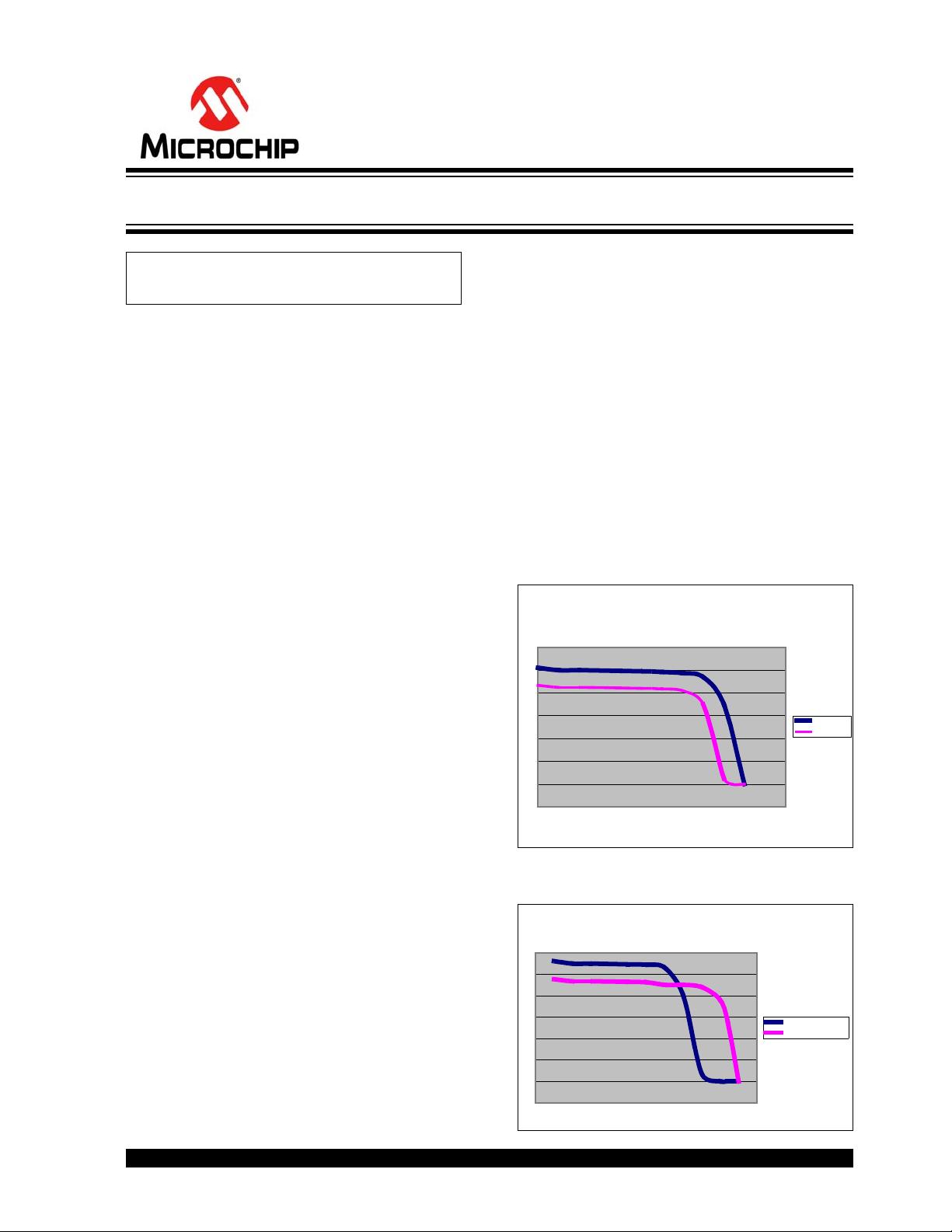
Figure 1 illustrates two characteristic I-V curves for a
solar panel under different lighting conditions. To get
the maximum power out of the panel, it is best to
operate the solar panel, on the knee of the curve.
From these graphs, you can see that depending on the
illumination of the panel, you want to operate the panel
at different load points to maximize the output power.
To complicate things even further, solar panels will
have a negative V
OC temperature coefficient and a
positive J
SC temperature coefficient. Figure 2 shows
the change in the I-V curves when temperature is taken
into consideration.
The relationship between illumination and temperature
make it difficult to estimate the proper point at which to
operate the solar panel in order to maximize the output
power. To solve this problem, the Maximum Power
Point Converter continually measures and adjusts the
power out of the solar panel in order to operate the
panel at its maximum power point, independent of the
panel’s illumination or temperature.
FIGURE 1: SOLAR PANEL
ILLUMINATION I-V CURVE
FIGURE 2: SOLAR PANEL
TEMPERATURE I-V CURVE
Author: John Charais
Microchip Technology Inc.
Voltage Full Sun Partial Sun High Tem Low Temp
0 0.51 0.4335 0.561 0.47685
5 0.5 0.425 0.55 0.4675
10 0.5 0.425 0.55 0.4675
20 0.497 0.42245 0.5467 0.464695
25 0.495 0.42075 0.5445 0.462825
30 0.492 0.4182 0.53 0.4505
35 0.487 0.41 0.4 0.45
40 0.47 0.35 0.035 0.44
45 0.35 0.025 0 0.38
47 0.3 0 0 0.28
50 0 0 0
0
Solar Panel Illumination
I-V Curve
Voltage
Current
Full Sun
Partial Sun
Solar Panel Temperature
I-V Curve
Voltage
Current
High Temperatures
Low Temperatures
Maximum Power Solar Converter
AN1211
DS01211B-page 2 2010 Microchip Technology Inc.
OVERVIEW
For this project we will be using a 10-volt open circuit
solar panel with a short circuit current of 2.5 amps. With
an open circuit voltage of 10 volts, a boost converter is
needed to charge the 24-volt battery. See Figure 3.
FIGURE 3: BOOST CONVERTER
To get the solar panel to operate at its maximum power
point, there are a few items needed. First, in order to
know the output power of the solar panel, both the
current and voltage of the solar panel have to be
monitored. This will be accomplished by a high side
current monitor and simple resistor divider on the solar
panel’s output voltage. There also needs to be a way to
control the output power of the solar panel. This is done
by manipulating the panel’s output current. And lastly,
a software algorithm is needed to know which way to
manipulate the current (e.g., whether the current out of
the solar panel should be increased or decreased).
To make the Maximum Power Point Converter work,
the functions of the boost converter need to be merged
with the solar panel’s output load. The boost converter
is either storing current in the boost inductor (switch
closed) or it is delivering current from the boost inductor
to the load (switch opened). When the boost inductor is
storing current, the current comes from the solar panel.
In essence, the boost inductor is the solar panel’s load.
By making the current stored in the boost inductor
programmable, the load of the solar panel becomes
programmable. This is the principal on how the
Maximum Power Point Converter works. The Maximum
Power Point Converter combines a boost converter, a
programmable current oscillator and a software
algorithm to maximize the power out of a solar panel.
HARDWARE OVERVIEW
Figure 4 shows the block diagram of the Maximum
Power Point Converter.
FIGURE 4: MAXIMUM POWER POINT CONVERTER
Battery
Solar
Panel
Solar Panel
Current Sense
Boost Supply
Output
Voltage Sense
Oscillator
Over-Voltage
Programmable
Max Power
Protection
Algorithm
Voltage Reference
PIC16F690
通过改变Boost电路
中电感存储的电流,
就可以改变太阳能组
件的负载。
为了能使太阳能组件工作在最大功率点,需要以下几点,第一,太阳能组件的电压和电流,
以便得到太阳能组件的输出功率。可由一个high-siede-current-monitor电路采样电流,
以及一个简单的电阻分压器采样电压来完成。另外,还需要一个可以控制太阳能组件输出
功率的方法,可通过改变太阳能组件的输出电流来实现。最后,必须要有软件算法,这个
算法需知道何时增加输出电流何时减小输出电流。
2010 Microchip Technology Inc. DS01211B-page 3
AN1211
THE CURRENT SENSE
To know the instantaneous current in the boost
inductor, a current sense resistor has been added in
series with the boost inductor. Knowing the value of the
current sense resistor and the voltage drop across it,
the current in the inductor is obtained. The current
sense resistor in our application is 10 mOhm. The
sense resistor is kept intentionally small to reduce the
inefficiency that it introduces to the boost converter. A
high side current monitor is used to generate a voltage
that is in the common mode range of the comparator.
THE OSCILLATOR
Figure 5 shows how the current sense works with a
comparator and the components of the boost supply to
make the oscillator.
The start-up condition of the oscillator is dictated by the
software of the PIC16F690. Before the comparator is
enabled, the port pin holds the gate of the boost FET
low while the oscillator’s reference voltage stabilizes.
Once the reference voltage is stable, the comparator is
enabled. This creates a start-up condition with no
voltage at the negative comparator input while the
positive input will be V
OSC_REF multiplied by the divider
ratio provided by R
SOURCE and RHYSTERESIS.
FIGURE 5: SIMPLIFIED DIAGRAM OF
THE BOOST OSCILLATOR
After the comparator is enabled, the positive input will
be greater than the negative input, which causes the
output of the comparator to immediately change to an
output high. When the output of the comparator is high,
the following will occur:
• The FET of the boost converter conducts.
• The positive input of the comparator equals V
HH
(see Equation 1).
• Energy is stored in the boost inductor.
• The current in the boost inductor increases at a
linear rate.
• The voltage on the negative input of the
comparator increases.
EQUATION 1:
At a predetermined current in the inductor, the negative
input of the comparator becomes greater than the pos-
itive input, which causes the output of the comparator
to become low. This current, I
HH (for hysteresis high), is
calculated by the following formula (Equation 2), where
Gm is the gain of the current monitor:
EQUATION 2:
When the output of the comparator is low, the following
will occur:
• The FET of the boost converter does not conduct.
• The positive input of the comparator equals V
HL
(see Equation 3).
• Energy is taken out of the boost inductor and
delivered to the 24-volt load.
• The current in the boost inductor decreases at a
linear rate.
• The voltage on the negative input of the
comparator decreases.
EQUATION 3:
The current in the inductor will keep decreasing until
the voltage on the negative input equals the positive
input of the comparator. This current, I
HL (for hysteresis
low), is calculated by the formula in Equation 4.
EQUATION 4:
When this point is reached, the comparator’s output
changes to a high and the cycle repeats.
Current
Monitor
RSENSE
Osc. Output
R
HYSTERISIS
RSOURCE
VOSC_REF
C1
-
+
V
IN
VOUT
V
HH
= V
OSC
_
REF
+ (V
DD
– V
OSC
_
REF
) * R
SOURCE
/(R
SOURCE
+ R
HYSTERESIS
)
IHH = VHH /(GM * RSENSE)
VHL = VOSC_REF * RHYSTERESIS/(RSOURCE + RHYSTERESIS)
IHL = VHL / (GM * RSENSE)
瞬时值
PWM
?
剩余13页未读,继续阅读
eagle_lee58
- 粉丝: 2
- 资源: 3
上传资源 快速赚钱
- 我的内容管理 收起
- 我的资源 快来上传第一个资源
- 我的收益 登录查看自己的收益
- 我的积分 登录查看自己的积分
- 我的C币 登录后查看C币余额
- 我的收藏
- 我的下载
- 下载帮助
会员权益专享
最新资源
- c++校园超市商品信息管理系统课程设计说明书(含源代码) (2).pdf
- 建筑供配电系统相关课件.pptx
- 企业管理规章制度及管理模式.doc
- vb打开摄像头.doc
- 云计算-可信计算中认证协议改进方案.pdf
- [详细完整版]单片机编程4.ppt
- c语言常用算法.pdf
- c++经典程序代码大全.pdf
- 单片机数字时钟资料.doc
- 11项目管理前沿1.0.pptx
- 基于ssm的“魅力”繁峙宣传网站的设计与实现论文.doc
- 智慧交通综合解决方案.pptx
- 建筑防潮设计-PowerPointPresentati.pptx
- SPC统计过程控制程序.pptx
- SPC统计方法基础知识.pptx
- MW全能培训汽轮机调节保安系统PPT教学课件.pptx
资源上传下载、课程学习等过程中有任何疑问或建议,欢迎提出宝贵意见哦~我们会及时处理!
点击此处反馈
安全验证
文档复制为VIP权益,开通VIP直接复制
信息提交成功
评论1