

CHAPTER
Send document comments to nexus7k-docfeedback@cisco.com
9-1
Cisco Nexus 7000 Series NX-OS Interfaces Configuration Guide, Release 5.x
OL-23435-03
9
Configuring Q-in-Q VLAN Tunnels
This chapter describes how to configure IEEE 802.1Q-in-Q (Q-in-Q) VLAN tunnels and Layer 2
protocol tunneling on Cisco NX-OS devices.
This chapter includes the following sections:
• Information About Q-in-Q Tunnels, page 9-1
• Information About Layer 2 Protocol Tunneling, page 9-4
• Licensing Requirements for Q-in-Q Tunnels, page 9-6
• Guidelines and Limitations, page 9-6
• Configuring Q-in-Q Tunnels and Layer 2 Protocol Tunneling, page 9-7
• Verifying the Q-in-Q Configuration, page 9-15
• Configuration Examples for Q-in-Q and Layer 2 Protocol Tunneling, page 9-15
• Feature History for Q-in-Q Tunnels and Layer 2 Protocol Tunneling, page 9-16
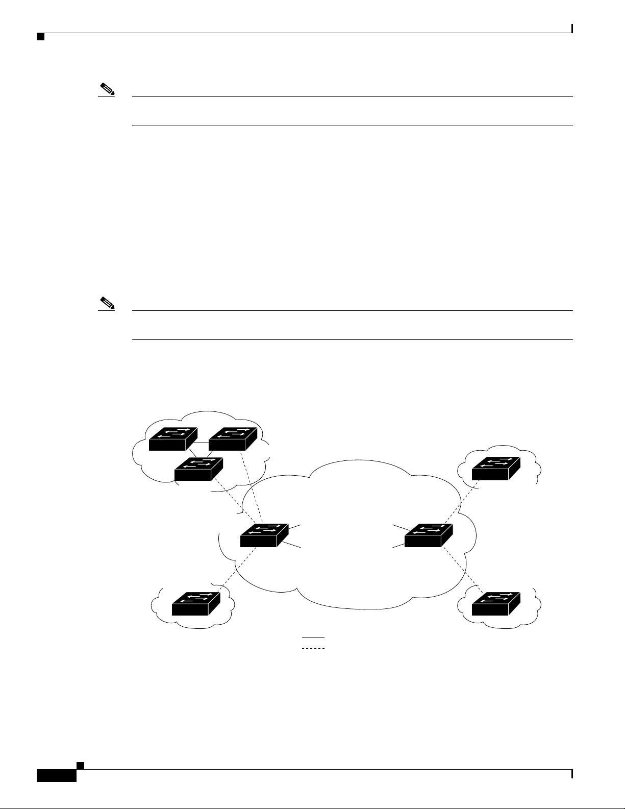
Information About Q-in-Q Tunnels
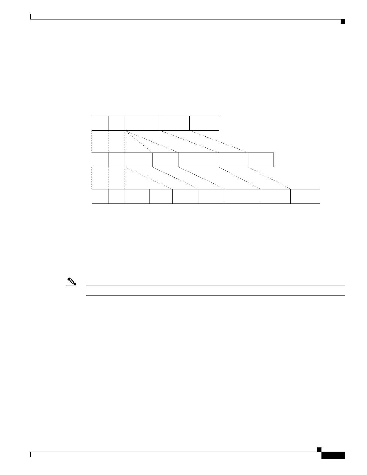
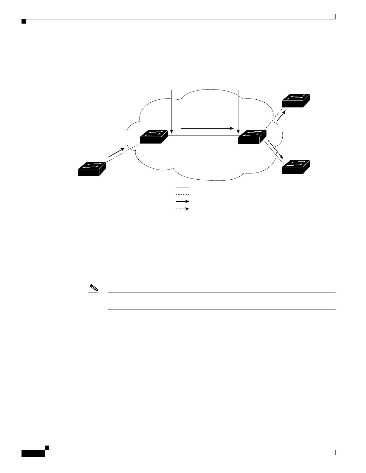
A Q-in-Q VLAN tunnel enables a service provider to segregate the traffic of different customers in their
infrastructure, while still giving the customer a full range of VLANs for their internal use by adding a
second 802.1Q tag to an already tagged frame.
This section includes the following topics:
• Q-in-Q Tunneling, page 9-1
• Native VLAN Hazard, page 9-3
Q-in-Q Tunneling
Business customers of service providers often have specific requirements for VLAN IDs and the number
of VLANs to be supported. The VLAN ranges required by different customers in the same
service-provider network might overlap, and traffic of customers through the infrastructure might be
mixed. Assigning a unique range of VLAN IDs to each customer would restrict customer configurations
and could easily exceed the VLAN limit of 4096 of the 802.1Q specification.
剩余15页未读,继续阅读

豆逗乐
- 粉丝: 0
- 资源: 3
 我的内容管理
收起
我的内容管理
收起
- 我的资源
快来上传第一个资源
 我的收益 登录查看自己的收益
 我的积分
登录查看自己的积分
我的积分
登录查看自己的积分
 我的C币
登录后查看C币余额
我的C币
登录后查看C币余额
 我的收藏
我的收藏  我的下载
我的下载  下载帮助
下载帮助

会员权益专享


最新资源
- RTL8188FU-Linux-v5.7.4.2-36687.20200602.tar(20765).gz
- c++校园超市商品信息管理系统课程设计说明书(含源代码) (2).pdf
- 建筑供配电系统相关课件.pptx
- 企业管理规章制度及管理模式.doc
- vb打开摄像头.doc
- 云计算-可信计算中认证协议改进方案.pdf
- [详细完整版]单片机编程4.ppt
- c语言常用算法.pdf
- c++经典程序代码大全.pdf
- 单片机数字时钟资料.doc
- 11项目管理前沿1.0.pptx
- 基于ssm的“魅力”繁峙宣传网站的设计与实现论文.doc
- 智慧交通综合解决方案.pptx
- 建筑防潮设计-PowerPointPresentati.pptx
- SPC统计过程控制程序.pptx
- SPC统计方法基础知识.pptx
资源上传下载、课程学习等过程中有任何疑问或建议,欢迎提出宝贵意见哦~我们会及时处理!
点击此处反馈


评论0