没有合适的资源?快使用搜索试试~ 我知道了~
首页STM32L151技术手册
STM32L151技术手册
需积分: 50 1.8k 浏览量
更新于2023-05-24
评论 2
收藏 2.02MB PDF 举报
关于stm32l151单片机的硬件设计手册,可以快速了解其性能,指标等。
资源详情
资源评论
资源推荐

This is information on a product in full production.
January 2015 DocID17659 Rev 11 1/132
STM32L151x6/8/B
STM32L152x6/8/B
Ultra-low-power 32-bit MCU ARM
®
-based Cortex
®
-M3,
128KB Flash, 16KB SRAM, 4KB EEPROM, LCD, USB, ADC, DAC
Datasheet - production data
Features
• Ultra-low-power platform
– 1.65 V to 3.6 V power supply
– -40°C to 85°C/105°C temperature range
– 0.3 µA Standby mode (3 wakeup pins)
– 0.9 µA Standby mode + RTC
– 0.57 µA Stop mode (16 wakeup lines)
– 1.2 µA Stop mode + RTC
– 9 µA Low-power run mode
– 214 µA/MHz Run mode
– 10 nA ultra-low I/O leakage
– < 8 µs wakeup time
• Core: ARM
®
Cortex
®
-M3 32-bit CPU
– From 32 kHz up to 32 MHz max
– 1.25 DMIPS/MHz (Dhrystone 2.1)
– Memory protection unit
• Reset and supply management
– Ultra-safe, low-power BOR (brownout
reset) with 5 selectable thresholds
– Ultra-low-power POR/PDR
– Programmable voltage detector (PVD)
• Clock sources
– 1 to 24 MHz crystal oscillator
– 32 kHz oscillator for RTC with calibration
– High Speed Internal 16 MHz factory-
trimmed RC (+/- 1%)
– Internal low-power 37 kHz RC
– Internal multispeed low-power 65 kHz to
4.2 MHz
– PLL for CPU clock and USB (48 MHz)
• Pre-programmed bootloader
– USART supported
• Development support
– Serial wire debug supported
– JTAG and trace supported
• Up to 83 fast I/Os (73 I/Os 5V tolerant), all
mappable on 16 external interrupt vectors
• Memories
– Up to 128 KB Flash with ECC
– Up to 16 KB RAM
– Up to 4 KB of true EEPROM with ECC
– 80 Byte backup register
• LCD Driver (except STM32L151x/6/8/B
devices) for up to 8x40 segments
– Support contrast adjustment
– Support blinking mode
– Step-up converter on board
• Rich analog peripherals (down to 1.8 V)
– 12-bit ADC 1 Msps up to 24 channels
– 12-bit DAC 2 channels with output buffers
– 2x ultra-low-power-comparators
(window mode and wake up capability)
• DMA controller 7x channels
• 8x peripherals communication interface
– 1x USB 2.0 (internal 48 MHz PLL)
– 3x USART (ISO 7816, IrDA)
– 2x SPI 16 Mbits/s
– 2x I2C (SMBus/PMBus)
• 10x timers: 6x 16-bit with up to 4 IC/OC/PWM
channels, 2x 16-bit basic timers, 2x watchdog
timers (independent and window)
• Up to 20 capacitive sensing channels
supporting touchkey, linear and rotary touch
sensors
• CRC calculation unit, 96-bit unique ID
Table 1. Device summary
Reference Part number
STM32L151x6/8/B
STM32L151CB, STM32L151C8,
STM32L151C6, STM32L151RB,
STM32L151R8, STM32L151R6,
STM32L151VB, STM32L151V8
STM32L152x6/8/B
STM32L152CB, STM32L152C8,
STM32L152C6, STM32L152RB,
STM32L152R8, STM32L152R6,
STM32L152VB, STM32L152V8
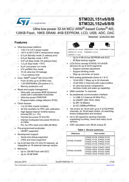
LQFP100 14 × 14 mm
LQFP64 10 × 10 mm
LQFP48 7 × 7 mm
UFBGA100 7 × 7 mm
TFBGA64 5 × 5 mm
UFQFPN48 7 × 7 mm
www.st.com

Contents STM32L151x6/8/B, STM32L152x6/8/B
2/132 DocID17659 Rev 11
Contents
1 Introduction . . . . . . . . . . . . . . . . . . . . . . . . . . . . . . . . . . . . . . . . . . . . . . . . 9
2 Description . . . . . . . . . . . . . . . . . . . . . . . . . . . . . . . . . . . . . . . . . . . . . . . . 10
2.1 Device overview . . . . . . . . . . . . . . . . . . . . . . . . . . . . . . . . . . . . . . . . . . . . .11
2.2 Ultra-low-power device continuum . . . . . . . . . . . . . . . . . . . . . . . . . . . . . . 12
2.2.1 Performance . . . . . . . . . . . . . . . . . . . . . . . . . . . . . . . . . . . . . . . . . . . . . 12
2.2.2 Shared peripherals . . . . . . . . . . . . . . . . . . . . . . . . . . . . . . . . . . . . . . . . 12
2.2.3 Common system strategy . . . . . . . . . . . . . . . . . . . . . . . . . . . . . . . . . . . 12
2.2.4 Features . . . . . . . . . . . . . . . . . . . . . . . . . . . . . . . . . . . . . . . . . . . . . . . . . 12
3 Functional overview . . . . . . . . . . . . . . . . . . . . . . . . . . . . . . . . . . . . . . . . 13
3.1 Low power modes . . . . . . . . . . . . . . . . . . . . . . . . . . . . . . . . . . . . . . . . . . 14
3.2 ARM
®
Cortex
®
-M3 core with MPU . . . . . . . . . . . . . . . . . . . . . . . . . . . . . . 18
3.3 Reset and supply management . . . . . . . . . . . . . . . . . . . . . . . . . . . . . . . . 19
3.3.1 Power supply schemes . . . . . . . . . . . . . . . . . . . . . . . . . . . . . . . . . . . . . 19
3.3.2 Power supply supervisor . . . . . . . . . . . . . . . . . . . . . . . . . . . . . . . . . . . . 19
3.3.3 Voltage regulator . . . . . . . . . . . . . . . . . . . . . . . . . . . . . . . . . . . . . . . . . . 20
3.3.4 Boot modes . . . . . . . . . . . . . . . . . . . . . . . . . . . . . . . . . . . . . . . . . . . . . . 20
3.4 Clock management . . . . . . . . . . . . . . . . . . . . . . . . . . . . . . . . . . . . . . . . . 21
3.5 Low power real-time clock and backup registers . . . . . . . . . . . . . . . . . . . 23
3.6 GPIOs (general-purpose inputs/outputs) . . . . . . . . . . . . . . . . . . . . . . . . . 23
3.7 Memories . . . . . . . . . . . . . . . . . . . . . . . . . . . . . . . . . . . . . . . . . . . . . . . . . 24
3.8 DMA (direct memory access) . . . . . . . . . . . . . . . . . . . . . . . . . . . . . . . . . . 24
3.9 LCD (liquid crystal display) . . . . . . . . . . . . . . . . . . . . . . . . . . . . . . . . . . . . 24
3.10 ADC (analog-to-digital converter) . . . . . . . . . . . . . . . . . . . . . . . . . . . . . . . 25
3.10.1 Temperature sensor . . . . . . . . . . . . . . . . . . . . . . . . . . . . . . . . . . . . . . . . 25
3.10.2 Internal voltage reference (V
REFINT
) . . . . . . . . . . . . . . . . . . . . . . . . . . . 25
3.11 DAC (digital-to-analog converter) . . . . . . . . . . . . . . . . . . . . . . . . . . . . . . . 25
3.12 Ultra-low-power comparators and reference voltage . . . . . . . . . . . . . . . . 26
3.13 Routing interface . . . . . . . . . . . . . . . . . . . . . . . . . . . . . . . . . . . . . . . . . . . 26
3.14 Touch sensing . . . . . . . . . . . . . . . . . . . . . . . . . . . . . . . . . . . . . . . . . . . . . 26
3.15 Timers and watchdogs . . . . . . . . . . . . . . . . . . . . . . . . . . . . . . . . . . . . . . . 27

DocID17659 Rev 11 3/132
STM32L151x6/8/B, STM32L152x6/8/B Contents
4
3.15.1 General-purpose timers (TIM2, TIM3, TIM4, TIM9, TIM10 and TIM11) . 28
3.15.2 Basic timers (TIM6 and TIM7) . . . . . . . . . . . . . . . . . . . . . . . . . . . . . . . . 28
3.15.3 SysTick timer . . . . . . . . . . . . . . . . . . . . . . . . . . . . . . . . . . . . . . . . . . . . . 28
3.15.4 Independent watchdog (IWDG) . . . . . . . . . . . . . . . . . . . . . . . . . . . . . . . 28
3.15.5 Window watchdog (WWDG) . . . . . . . . . . . . . . . . . . . . . . . . . . . . . . . . . 29
3.16 Communication interfaces . . . . . . . . . . . . . . . . . . . . . . . . . . . . . . . . . . . . 29
3.16.1 I²C bus . . . . . . . . . . . . . . . . . . . . . . . . . . . . . . . . . . . . . . . . . . . . . . . . . . 29
3.16.2 Universal synchronous/asynchronous receiver transmitter (USART) . . 29
3.16.3 Serial peripheral interface (SPI) . . . . . . . . . . . . . . . . . . . . . . . . . . . . . . . 29
3.16.4 Universal serial bus (USB) . . . . . . . . . . . . . . . . . . . . . . . . . . . . . . . . . . . 29
3.17 CRC (cyclic redundancy check) calculation unit . . . . . . . . . . . . . . . . . . . 30
3.18 Development support . . . . . . . . . . . . . . . . . . . . . . . . . . . . . . . . . . . . . . . . 30
4 Pin descriptions . . . . . . . . . . . . . . . . . . . . . . . . . . . . . . . . . . . . . . . . . . . 31
5 Memory mapping . . . . . . . . . . . . . . . . . . . . . . . . . . . . . . . . . . . . . . . . . . . 48
6 Electrical characteristics . . . . . . . . . . . . . . . . . . . . . . . . . . . . . . . . . . . . 49
6.1 Parameter conditions . . . . . . . . . . . . . . . . . . . . . . . . . . . . . . . . . . . . . . . . 49
6.1.1 Minimum and maximum values . . . . . . . . . . . . . . . . . . . . . . . . . . . . . . . 49
6.1.2 Typical values . . . . . . . . . . . . . . . . . . . . . . . . . . . . . . . . . . . . . . . . . . . . 49
6.1.3 Typical curves . . . . . . . . . . . . . . . . . . . . . . . . . . . . . . . . . . . . . . . . . . . . 49
6.1.4 Loading capacitor . . . . . . . . . . . . . . . . . . . . . . . . . . . . . . . . . . . . . . . . . 49
6.1.5 Pin input voltage . . . . . . . . . . . . . . . . . . . . . . . . . . . . . . . . . . . . . . . . . . 49
6.1.6 Power supply scheme . . . . . . . . . . . . . . . . . . . . . . . . . . . . . . . . . . . . . . 50
6.1.7 Optional LCD power supply scheme . . . . . . . . . . . . . . . . . . . . . . . . . . . 51
6.1.8 Current consumption measurement . . . . . . . . . . . . . . . . . . . . . . . . . . . 51
6.2 Absolute maximum ratings . . . . . . . . . . . . . . . . . . . . . . . . . . . . . . . . . . . . 52
6.3 Operating conditions . . . . . . . . . . . . . . . . . . . . . . . . . . . . . . . . . . . . . . . . 53
6.3.1 General operating conditions . . . . . . . . . . . . . . . . . . . . . . . . . . . . . . . . . 53
6.3.2 Embedded reset and power control block characteristics . . . . . . . . . . . 54
6.3.3 Embedded internal reference voltage . . . . . . . . . . . . . . . . . . . . . . . . . . 56
6.3.4 Supply current characteristics . . . . . . . . . . . . . . . . . . . . . . . . . . . . . . . . 57
6.3.5 Wakeup time from Low power mode . . . . . . . . . . . . . . . . . . . . . . . . . . . 69
6.3.6 External clock source characteristics . . . . . . . . . . . . . . . . . . . . . . . . . . . 70
6.3.7 Internal clock source characteristics . . . . . . . . . . . . . . . . . . . . . . . . . . . 75
6.3.8 PLL characteristics . . . . . . . . . . . . . . . . . . . . . . . . . . . . . . . . . . . . . . . . 77

Contents STM32L151x6/8/B, STM32L152x6/8/B
4/132 DocID17659 Rev 11
6.3.9 Memory characteristics . . . . . . . . . . . . . . . . . . . . . . . . . . . . . . . . . . . . . 78
6.3.10 EMC characteristics . . . . . . . . . . . . . . . . . . . . . . . . . . . . . . . . . . . . . . . . 79
6.3.11 Electrical sensitivity characteristics . . . . . . . . . . . . . . . . . . . . . . . . . . . . 81
6.3.12 I/O current injection characteristics . . . . . . . . . . . . . . . . . . . . . . . . . . . . 81
6.3.13 I/O port characteristics . . . . . . . . . . . . . . . . . . . . . . . . . . . . . . . . . . . . . . 83
6.3.14 NRST pin characteristics . . . . . . . . . . . . . . . . . . . . . . . . . . . . . . . . . . . . 86
6.3.15 TIM timer characteristics . . . . . . . . . . . . . . . . . . . . . . . . . . . . . . . . . . . . 87
6.3.16 Communication interfaces . . . . . . . . . . . . . . . . . . . . . . . . . . . . . . . . . . . 88
6.3.17 12-bit ADC characteristics . . . . . . . . . . . . . . . . . . . . . . . . . . . . . . . . . . . 94
6.3.18 DAC electrical specifications . . . . . . . . . . . . . . . . . . . . . . . . . . . . . . . . 100
6.3.19 Temperature sensor characteristics . . . . . . . . . . . . . . . . . . . . . . . . . . . 102
6.3.20 Comparator . . . . . . . . . . . . . . . . . . . . . . . . . . . . . . . . . . . . . . . . . . . . . 103
6.3.21 LCD controller (STM32L152xx only) . . . . . . . . . . . . . . . . . . . . . . . . . . 105
7 Package characteristics . . . . . . . . . . . . . . . . . . . . . . . . . . . . . . . . . . . . 106
7.1 Package mechanical data . . . . . . . . . . . . . . . . . . . . . . . . . . . . . . . . . . . 106
7.2 Thermal characteristics . . . . . . . . . . . . . . . . . . . . . . . . . . . . . . . . . . . . . 123
7.2.1 Reference document . . . . . . . . . . . . . . . . . . . . . . . . . . . . . . . . . . . . . . 124
8 Part numbering . . . . . . . . . . . . . . . . . . . . . . . . . . . . . . . . . . . . . . . . . . . 125
9 Revision history . . . . . . . . . . . . . . . . . . . . . . . . . . . . . . . . . . . . . . . . . . 126

DocID17659 Rev 11 5/132
STM32L151x6/8/B, STM32L152x6/8/B List of tables
6
List of tables
Table 1. Device summary . . . . . . . . . . . . . . . . . . . . . . . . . . . . . . . . . . . . . . . . . . . . . . . . . . . . . . . . . . 1
Table 2. Ultra-low-power STM32L151x6/8/B and STM32L152x6/8/B device features and
peripheral counts . . . . . . . . . . . . . . . . . . . . . . . . . . . . . . . . . . . . . . . . . . . . . . . . . . . . . . . . 11
Table 3. Functionalities depending on the operating power supply range . . . . . . . . . . . . . . . . . . . . 15
Table 4. CPU frequency range depending on dynamic voltage scaling . . . . . . . . . . . . . . . . . . . . . . 16
Table 5. Working mode-dependent functionalities (from Run/active down to standby) . . . . . . . . . . 17
Table 6. Timer feature comparison . . . . . . . . . . . . . . . . . . . . . . . . . . . . . . . . . . . . . . . . . . . . . . . . . . 27
Table 7. Legend/abbreviations used in the pinout table . . . . . . . . . . . . . . . . . . . . . . . . . . . . . . . . . . 36
Table 8. STM32L151x6/8/B and STM32L152x6/8/B pin definitions . . . . . . . . . . . . . . . . . . . . . . . . . 37
Table 9. Alternate function input/output . . . . . . . . . . . . . . . . . . . . . . . . . . . . . . . . . . . . . . . . . . . . . . 43
Table 10. Voltage characteristics . . . . . . . . . . . . . . . . . . . . . . . . . . . . . . . . . . . . . . . . . . . . . . . . . . . . 52
Table 11. Current characteristics . . . . . . . . . . . . . . . . . . . . . . . . . . . . . . . . . . . . . . . . . . . . . . . . . . . . 52
Table 12. Thermal characteristics. . . . . . . . . . . . . . . . . . . . . . . . . . . . . . . . . . . . . . . . . . . . . . . . . . . . 53
Table 13. General operating conditions . . . . . . . . . . . . . . . . . . . . . . . . . . . . . . . . . . . . . . . . . . . . . . . 53
Table 14. Embedded reset and power control block characteristics. . . . . . . . . . . . . . . . . . . . . . . . . . 54
Table 15. Embedded internal reference voltage calibration values . . . . . . . . . . . . . . . . . . . . . . . . . . 56
Table 16. Embedded internal reference voltage . . . . . . . . . . . . . . . . . . . . . . . . . . . . . . . . . . . . . . . . . 56
Table 17. Current consumption in Run mode, code with data processing running from Flash. . . . . . 58
Table 18. Current consumption in Run mode, code with data processing running from RAM . . . . . . 59
Table 19. Current consumption in Sleep mode . . . . . . . . . . . . . . . . . . . . . . . . . . . . . . . . . . . . . . . . . 60
Table 20. Current consumption in Low power run mode . . . . . . . . . . . . . . . . . . . . . . . . . . . . . . . . . . 62
Table 21. Current consumption in Low power sleep mode. . . . . . . . . . . . . . . . . . . . . . . . . . . . . . . . . 63
Table 22. Typical and maximum current consumptions in Stop mode . . . . . . . . . . . . . . . . . . . . . . . . 64
Table 23. Typical and maximum current consumptions in Standby mode . . . . . . . . . . . . . . . . . . . . . 66
Table 24. Peripheral current consumption . . . . . . . . . . . . . . . . . . . . . . . . . . . . . . . . . . . . . . . . . . . . . 67
Table 25. Low-power mode wakeup timings . . . . . . . . . . . . . . . . . . . . . . . . . . . . . . . . . . . . . . . . . . . 69
Table 26. High-speed external user clock characteristics. . . . . . . . . . . . . . . . . . . . . . . . . . . . . . . . . . 70
Table 27. Low-speed external user clock characteristics . . . . . . . . . . . . . . . . . . . . . . . . . . . . . . . . . . 71
Table 28. HSE oscillator characteristics . . . . . . . . . . . . . . . . . . . . . . . . . . . . . . . . . . . . . . . . . . . . . . . 72
Table 29. LSE oscillator characteristics (f
LSE
= 32.768 kHz) . . . . . . . . . . . . . . . . . . . . . . . . . . . . . . . 73
Table 30. HSI oscillator characteristics. . . . . . . . . . . . . . . . . . . . . . . . . . . . . . . . . . . . . . . . . . . . . . . . 75
Table 31. LSI oscillator characteristics . . . . . . . . . . . . . . . . . . . . . . . . . . . . . . . . . . . . . . . . . . . . . . . . 75
Table 32. MSI oscillator characteristics . . . . . . . . . . . . . . . . . . . . . . . . . . . . . . . . . . . . . . . . . . . . . . . 76
Table 33. PLL characteristics . . . . . . . . . . . . . . . . . . . . . . . . . . . . . . . . . . . . . . . . . . . . . . . . . . . . . . . 77
Table 34. RAM and hardware registers . . . . . . . . . . . . . . . . . . . . . . . . . . . . . . . . . . . . . . . . . . . . . . . 78
Table 35. Flash memory and data EEPROM characteristics . . . . . . . . . . . . . . . . . . . . . . . . . . . . . . . 78
Table 36. Flash memory, data EEPROM endurance and data retention . . . . . . . . . . . . . . . . . . . . . . 79
Table 37. EMS characteristics . . . . . . . . . . . . . . . . . . . . . . . . . . . . . . . . . . . . . . . . . . . . . . . . . . . . . . 79
Table 38. EMI characteristics . . . . . . . . . . . . . . . . . . . . . . . . . . . . . . . . . . . . . . . . . . . . . . . . . . . . . . . 80
Table 39. ESD absolute maximum ratings . . . . . . . . . . . . . . . . . . . . . . . . . . . . . . . . . . . . . . . . . . . . . 81
Table 40. Electrical sensitivities . . . . . . . . . . . . . . . . . . . . . . . . . . . . . . . . . . . . . . . . . . . . . . . . . . . . . 81
Table 41. I/O current injection susceptibility . . . . . . . . . . . . . . . . . . . . . . . . . . . . . . . . . . . . . . . . . . . . 82
Table 42. I/O static characteristics . . . . . . . . . . . . . . . . . . . . . . . . . . . . . . . . . . . . . . . . . . . . . . . . . . . 83
Table 43. Output voltage characteristics . . . . . . . . . . . . . . . . . . . . . . . . . . . . . . . . . . . . . . . . . . . . . . 84
Table 44. I/O AC characteristics . . . . . . . . . . . . . . . . . . . . . . . . . . . . . . . . . . . . . . . . . . . . . . . . . . . . . 85
Table 45. NRST pin characteristics . . . . . . . . . . . . . . . . . . . . . . . . . . . . . . . . . . . . . . . . . . . . . . . . . . 86
Table 46. TIMx characteristics . . . . . . . . . . . . . . . . . . . . . . . . . . . . . . . . . . . . . . . . . . . . . . . . . . . . . . 87
Table 47. I
2
C characteristics. . . . . . . . . . . . . . . . . . . . . . . . . . . . . . . . . . . . . . . . . . . . . . . . . . . . . . . . 88
剩余131页未读,继续阅读


安全验证
文档复制为VIP权益,开通VIP直接复制

评论0