没有合适的资源?快使用搜索试试~ 我知道了~
首页NEO-M8-HardwareIntegrationManual.pdf
NEO-M8-HardwareIntegrationManual.pdf
需积分: 9 27 下载量 152 浏览量
更新于2023-05-28
评论 1
收藏 1.05MB PDF 举报
NEO-M8-HardwareIntegrationManual.pdf,NEO-M8P硬件设计参考,支持RTK
资源详情
资源评论
资源推荐
NEO-M8 - Hardware Integration Manual
Page 2 of 26
UBX-13003557 - R01 Objective Specification
Document Information
Title NEO-M8
Subtitle u-blox M8 GNSS modules
Document type Hardware Integration Manual
Document number UBX-13003557
Document revision R01
Document status Objective Specification
Document status information
Objective
Specification
This document contains target values. Revised and supplementary data will be published
later.
Advance
Information
This document contains data based on early testing. Revised and supplementary data will be
published later.
Early Production
Information
This document contains data from product verification. Revised and supplementary data
may be published later.
Production
Information
This document contains the final product specification.
This document applies to the following products:
Name Type number ROM/FLASH version PCN reference
NEO-M8N-0 NEO-M8N-0-00
Boot ROM 0.22 / 2.00
N/A
This document and the use of any information contained therein, is subject to the acceptance of the u-blox terms and conditions. They
can be downloaded from www.u-blox.com.
u-blox makes no warranties based on the accuracy or completeness of the contents of this document and reserves the right to make
changes to specifications and product descriptions at any time without notice.
u-blox reserves all rights to this document and the information contained herein. Reproduction, use or disclosure to third parties without
express permission is strictly prohibited. Copyright © 2013, u-blox AG.
u-blox
®
is a registered trademark of u-blox Holding AG in the EU and other countries. ARM
®
is the registered trademark of ARM Limited in
the EU and other countries.
NEO-M8 - Hardware Integration Manual
Contents
UBX-13003557 - R01 Objective Specification Page 3 of 26
Contents
Contents .............................................................................................................................. 3
1 Hardware description .................................................................................................. 4
1.1 Overview .............................................................................................................................................. 4
1.2 Configuration ....................................................................................................................................... 4
1.3 Connecting power ................................................................................................................................ 4
1.4 Interfaces .............................................................................................................................................. 5
1.5 I/O pins ................................................................................................................................................. 7
2 Design ........................................................................................................................... 8
2.1 Pin description ...................................................................................................................................... 8
2.2 Minimal design ..................................................................................................................................... 9
2.3 Layout: Footprint and paste mask ......................................................................................................... 9
2.4 Antenna ............................................................................................................................................. 10
3 Migration to u-blox M8 modules .............................................................................. 13
3.1 Migrating u-blox 7 designs to a u-blox M8 module ............................................................................. 13
3.2 Software migration ............................................................................................................................. 13
3.3 Hardware migration NEO-6 -> NEO-M8 .............................................................................................. 13
4 Product handling ........................................................................................................ 15
4.1 Packaging, shipping, storage and moisture preconditioning ............................................................... 15
4.2 Soldering ............................................................................................................................................ 15
4.3 EOS/ESD/EMI precautions ................................................................................................................... 19
4.4 Applications with wireless modules LEON / LISA ................................................................................. 22
Appendix .......................................................................................................................... 24
Recommended parts ...................................................................................................................................... 24
Related documents........................................................................................................... 25
Revision history ................................................................................................................ 25
Contact .............................................................................................................................. 26
NEO-M8 - Hardware Integration Manual
Hardware description
UBX-13003557 - R01 Objective Specification Page 4 of 26
1 Hardware description
1.1 Overview
u-blox M8 modules are standalone GNSS positioning modules featuring the high performance u-blox M8
positioning engine. Available in industry standard form factors in leadless chip carrier (LCC) packages, they are
easy to integrate and combine exceptional positioning performance with highly flexible power, design, and
connectivity options. SMT pads allow fully automated assembly with standard pick & place and reflow-soldering
equipment for cost-efficient, high-volume production enabling short time-to-market.
For product features see the NEO-M8 Data Sheet [1].
To determine which u-blox product best meets your needs, see the product selector tables on the u-blox
website www.u-blox.com.
1.2 Configuration
The configuration settings can be modified using UBX protocol configuration messages, see u-blox M8-V15
Receiver Description Protocol Spec [2]. The modified settings remain effective until power-down or reset. If
these settings have been stored in BBR (Battery Backed RAM), then the modified configuration will be retained,
as long as the backup battery supply is not interrupted.
For NEO-M8N module, configuration can be saved permanently in SQI flash.
1.3 Connecting power
u-blox M8 positioning modules have up to three power supply pins: VCC, V_BCKP and VDD_USB.
VCC: Main supply voltage
The VCC pin provides the main supply voltage. During operation, the current drawn by the module can vary by
some orders of magnitude, especially if enabling low-power operation modes. For this reason, it is important
that the supply circuitry be able to support the peak power for a short time (see the NEO-M8 Data Sheet [1] for
specification).
When switching from backup mode (see section 1.3.2) to normal operation or at start-up, u-blox M8
modules must charge the internal capacitors in the core domain. In certain situations, this can result in a
significant current draw. For low power applications using Power Save and backup modes it is important
that the power supply or low ESR capacitors at the module input can deliver this current/charge.
Use a proper GND concept. Do not use any resistors or coils in the power line.
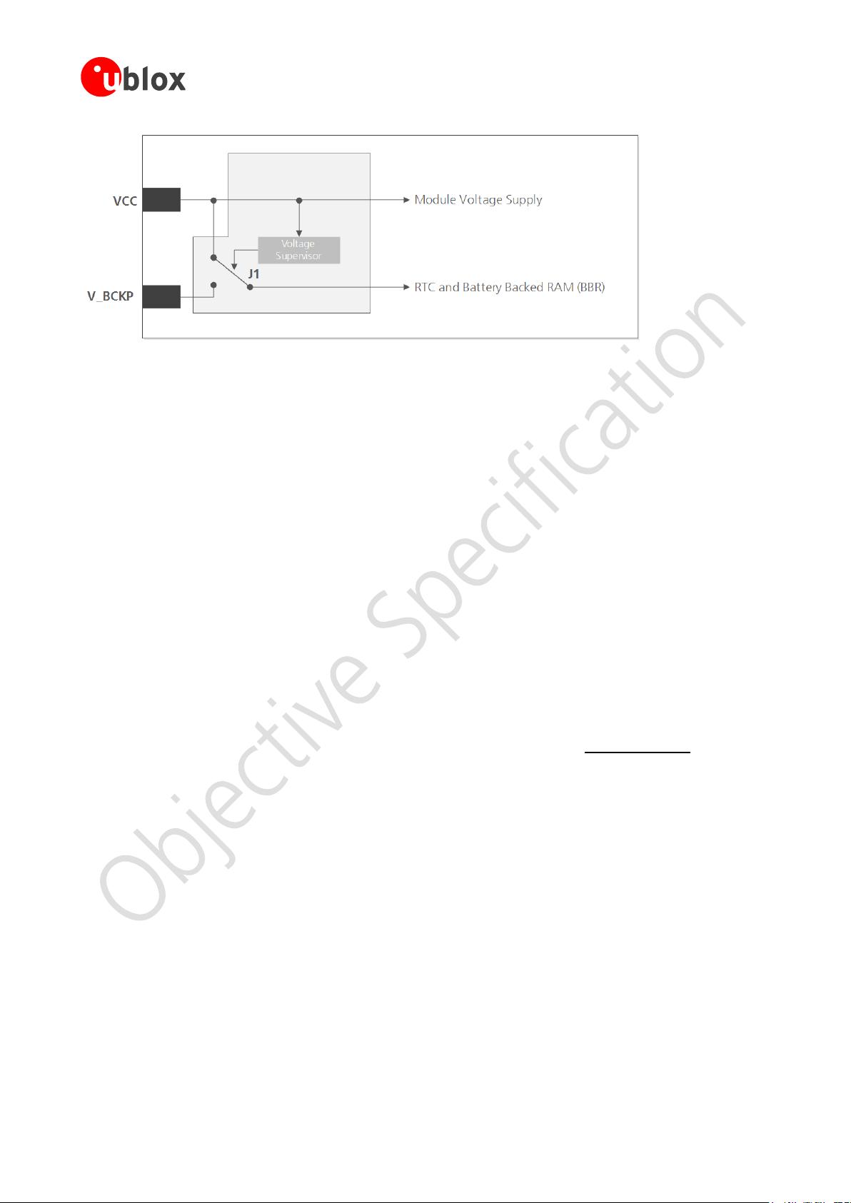
V_BCKP: Backup supply voltage
If there is a power failure on the module supply, the real-time clock (RTC) and battery backed RAM (BBR) are
supplied through the V_BCKP pin. Use of valid time and the GNSS orbit data at start up will improve the GNSS
performance, as with hot starts, warm starts, AssistNow Autonomous and AssistNow Offline. If no backup
battery is connected, the module performs a cold start at power up.
Avoid high resistance on the V_BCKP line: During the switch from main supply to backup supply a short
current adjustment peak can cause high voltage drop on the pin with possible malfunctions.
If no backup supply voltage is available, connect the V_BCKP pin to VCC.
As long as power is supplied to the u-blox M8 module through the VCC pin, the backup battery is
disconnected from the RTC and the BBR to avoid unnecessary battery drain (see Figure 1). In this case,
VCC supplies power to the RTC and BBR.
NEO-M8 - Hardware Integration Manual
Hardware description
UBX-13003557 - R01 Objective Specification Page 5 of 26
Figure 1: Backup battery and voltage (for exact pin orientation, see data sheet)
VCC_RF: Output voltage RF
The VCC_RF pin can supply an active antenna or external LNA. For more information, see section 2.2
1.4 Interfaces
UART
u-blox M8 positioning modules include a Universal Asynchronous Receiver Transmitter (UART) serial interface
RxD/TxD supporting configurable baud rates. The baud rates supported are specified in the NEO-M8 Data Sheet
[1]
The signal output and input levels are 0 V to VCC. An interface based on RS232 standard levels (+/- 12 V) can be
implemented using level shifters such as Maxim MAX3232. Hardware handshake signals and synchronous
operation are not supported.
USB
A USB version 2.0 FS (Full Speed, 12 Mb/s) compatible interface is available for communication as an alternative
to the UART. The USB_DP integrates a pull-up resistor to signal a full-speed device to the host. The VDD_USB
pin supplies the USB interface.
u-blox provides Microsoft® certified USB drivers for Windows XP, Windows Vista, and Windows 7 operating
systems (also Windows 8 compatible). These drivers are available at our website at
www.u-blox.com
USB external components
The USB interface requires some external components to implement the physical characteristics required by the
USB 2.0 specification. These external components are shown in Figure 2
and listed in Table 1. To comply with
USB specifications, VBUS must be connected through an LDO (U1) to pin VDD_USB on the module.
If the USB device is self-powered, the power supply (VCC) can be turned off and the digital block is not
powered. In this case, since VBUS is still available, the USB host would still receive the signal indicating that the
device is present and ready to communicate. This should be avoided by disabling the LDO (U1) using the enable
signal (EN) of the VCC-LDO or the output of a voltage supervisor. Depending on the characteristics of the LDO
(U1) it is recommended to add a pull-down resistor (R11) at its output to ensure VDD_USB is not floating if the
LDO (U1) is disabled or the USB cable is not connected i.e. VBUS is not supplied.
If the device is bus-powered, LDO (U1) does not need an enable control.
剩余25页未读,继续阅读
dugujian6
- 粉丝: 3
- 资源: 5
上传资源 快速赚钱
- 我的内容管理 收起
- 我的资源 快来上传第一个资源
- 我的收益 登录查看自己的收益
- 我的积分 登录查看自己的积分
- 我的C币 登录后查看C币余额
- 我的收藏
- 我的下载
- 下载帮助
会员权益专享
最新资源
- RTL8188FU-Linux-v5.7.4.2-36687.20200602.tar(20765).gz
- c++校园超市商品信息管理系统课程设计说明书(含源代码) (2).pdf
- 建筑供配电系统相关课件.pptx
- 企业管理规章制度及管理模式.doc
- vb打开摄像头.doc
- 云计算-可信计算中认证协议改进方案.pdf
- [详细完整版]单片机编程4.ppt
- c语言常用算法.pdf
- c++经典程序代码大全.pdf
- 单片机数字时钟资料.doc
- 11项目管理前沿1.0.pptx
- 基于ssm的“魅力”繁峙宣传网站的设计与实现论文.doc
- 智慧交通综合解决方案.pptx
- 建筑防潮设计-PowerPointPresentati.pptx
- SPC统计过程控制程序.pptx
- SPC统计方法基础知识.pptx
资源上传下载、课程学习等过程中有任何疑问或建议,欢迎提出宝贵意见哦~我们会及时处理!
点击此处反馈
安全验证
文档复制为VIP权益,开通VIP直接复制
信息提交成功
评论0