

RTL8201BL
2002-03-29 Rev.1.2
1
REALTEK SINGLE CHIP
SINGLE PORT 10/100M
FAST ETHERNET PHYCEIVER
RTL8201BL
1. Features........................................................................... 2
2. General Description.......................................................2
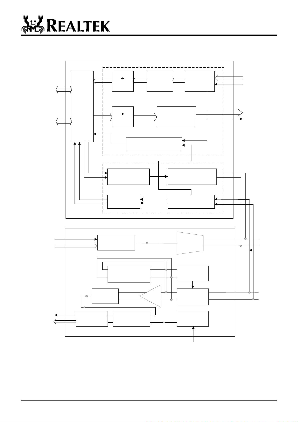
3. Block Diagram................................................................ 3
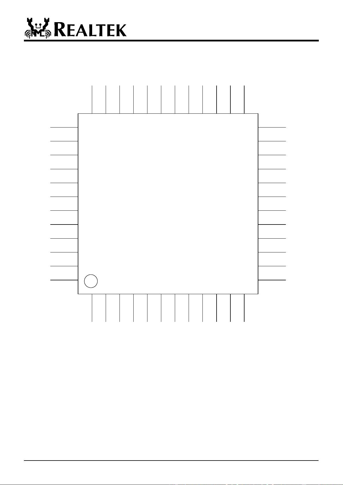
4. Pin Assignments .............................................................4
5. Pin Description...............................................................5
5.1 100 Mbps MII & PCS Interface ................................ 5
5.2 SNI (Serial Network Interface): 10Mbps only .......... 5
5.3 Clock Interface .......................................................... 6
5.4 100Mbps Network Interface...................................... 6
5.5 Device Configuration Interface................................. 6
5.6 LED Interface/PHY Address Config......................... 7
5.7 Reset and other pins .................................................. 7
5.8 Power and Ground pins ............................................. 7
6. Register Descriptions.....................................................8
6.1 Register 0 Basic Mode Control Register ................... 8
6.2 Register 1 Basic Mode Status Register ..................... 9
6.3. Register 2 PHY Identifier Register 1 ....................... 9
6.4. Register 3 PHY Identifier Register 2 ....................... 9
6.5. Register 4 Auto-negotiation Advertisement
Register(ANAR) ........................................................... 10
6.6 Register 5 Auto-Negotiation Link Partner Ability
Register(ANLPAR) ....................................................... 10
6.7 Register 6 Auto-negotiation Expansion
Register(ANER)............................................................ 11
6.8 Register 16 Nway Setup Register(NSR) ................. 11
6.9 Register 17 Loopback, Bypass, Receiver Error Mask
Register(LBREMR) ...................................................... 12
6.10 Register 18 RX_ER Counter(REC)....................... 12
6.11 Register 19 10Mbps Network Interface Configuration Register... 12
6.12 Register 20 PHY 1_1 Register .............................. 13
6.13 Register 21 PHY 1_2 Register .............................. 13
6.14 Register 22 PHY 2 Register .................................. 13
6.15 Register 23 Twister_1 Register ............................. 13
6.16 Register 24 Twister_2 Register ............................. 13
6.17 Register 25 Test Register....................................... 13
7. Functional Description ................................................ 14
7.1 MII and Management Interface............................... 14
7.1.1 Data Transition ................................................ 14
7.1.2 Serial Management.......................................... 14
7.2 Auto-negotiation and Parallel Detection ................. 15
7.3 Flow control support............................................... 16
7.4 Hardware Configuration and Auto-negotiation................. 16
7.5 LED and PHY Address Configuration.................... 17
7.6 Serial Network Interface ......................................... 17
7.7 Power Down, Link Down, Power Saving, and Isolation Modes ... 18
7.8 Media Interface....................................................... 18
7.8.1 100Base TX..................................................... 18
7.8.2 100Base-FX Fiber Mode Operation ................ 18
7.8.3 10Base Tx/Rx.................................................. 19
7.9 Repeater Mode Operation ....................................... 19
7.10 Reset, and Transmit Bias(RTSET) ........................ 19
7.11 3.3V power supply and voltage conversion circuit 19
7.12 Far End Fault Indication (FEFI)............................ 20
8. Electrical Characteristics............................................ 21
8.1 D.C. Characteristics ................................................ 21
8.1.1. Absolute Maximum Ratings........................... 21
8.1.2. Operating Conditions ..................................... 21
8.1.3. Power Dissipation........................................... 21
8.1.4 Supply Voltage: Vcc........................................ 21
8.2 A.C. Characteristics ................................................ 22
8.2.1 MII Timing of Transmission Cycle ................. 22
8.2.2 MII Timing of Reception Cycle ...................... 23
8.2.3 SNI Timing of Transmission Cycle ................. 24
8.2.4 SNI Timing of Reception Cycle ...................... 25
8.2.5 MDC/MDIO timing......................................... 26
8.2.6 Transmission Without Collision ...................... 26
8.2.7 Reception Without Error ................................. 26
8.3 Crystal and Transformer Specifications.................. 27
8.3.1 Crystal Specifications...................................... 27
8.3.2 Transformer Specifications.............................. 27
9. Mechanical Dimensions............................................... 28
10. Revision History......................................................... 29

剩余28页未读,继续阅读

qq_27293877
- 粉丝: 0
- 资源: 1
 我的内容管理
收起
我的内容管理
收起
- 我的资源
快来上传第一个资源
 我的收益 登录查看自己的收益
 我的积分
登录查看自己的积分
我的积分
登录查看自己的积分
 我的C币
登录后查看C币余额
我的C币
登录后查看C币余额
 我的收藏
我的收藏  我的下载
我的下载  下载帮助
下载帮助

会员权益专享


最新资源
- RTL8188FU-Linux-v5.7.4.2-36687.20200602.tar(20765).gz
- c++校园超市商品信息管理系统课程设计说明书(含源代码) (2).pdf
- 建筑供配电系统相关课件.pptx
- 企业管理规章制度及管理模式.doc
- vb打开摄像头.doc
- 云计算-可信计算中认证协议改进方案.pdf
- [详细完整版]单片机编程4.ppt
- c语言常用算法.pdf
- c++经典程序代码大全.pdf
- 单片机数字时钟资料.doc
- 11项目管理前沿1.0.pptx
- 基于ssm的“魅力”繁峙宣传网站的设计与实现论文.doc
- 智慧交通综合解决方案.pptx
- 建筑防潮设计-PowerPointPresentati.pptx
- SPC统计过程控制程序.pptx
- SPC统计方法基础知识.pptx
资源上传下载、课程学习等过程中有任何疑问或建议,欢迎提出宝贵意见哦~我们会及时处理!
点击此处反馈


评论0