没有合适的资源?快使用搜索试试~ 我知道了~
首页tracepro学习资料
tracepro学习资料
需积分: 16 11 下载量 171 浏览量
更新于2023-06-04
评论 2
收藏 1.38MB PDF 举报
光学设计软件Tracepro教程,TracePro® Tutorial Textured RepTile Backlight
资源详情
资源评论
资源推荐
TracePro Tutorial: Textured RepTile Backlight
TracePro
®
Tutorial
Textured RepTile Backlight
Copyright © 2007 – Lambda Research Corporation
All Rights Reserved
www.lambdares.com
Lambda Research Corporation 1
www.cadfamily.com EMail:cadserv21@hotmail.com
The document is for study only,if tort to your rights,please inform us,we will delete
TracePro Tutorial: Textured RepTile Backlight
Introduction
There are a number of optical systems that use small, repeated optical geometry to
perform. Examples include the structure for backlights, brightness enhancement films,
and lenslet arrays. RepTile within TracePro allows repetitive structure to be placed on
planar surfaces in a number of different patterns without the need to develop each one
of the geometry elements. This not only saves time during the development phase, but
also time during the ray trace analysis since the computation of intercepts with the
RepTile geometry is computed analytically rather than through intersections with
geometry. RepTile till now (i.e., prior to Version 4.0 of TracePro) has three cases:
• Constant: the RepTile geometry (e.g., sphere radius) is constant over the Tiles
(or cells) that extend across the RepTile boundary,
• Variable Rows: the RepTile geometry (e.g., sphere radius) can vary as a function
of the row number over the Tiles (or cells) that extend across the RepTile
boundary, and
• Parameterized: the RepTile geometry (e.g., sphere radius) can vary as a function
of both the row and column numbers over the Tiles (or cells) that extend across
the RepTile boundary.
All three of these make a single piece of geometry (e.g., a sphere) within a Tile (or cell)
that has both a width and height assigned to it. The cases allow more control of the
variation of the geometry as one goes down the bulleted list. However, in all cases the
RepTile geometry, in a sense, is deterministic, meaning there is no ability to have a
random array of RepTile geometry, multiple RepTiles per cell, and/or more complex
parameterizations for the placement and shape of the RepTiles.
The development of backlights for LCD displays is typically based on proprietary and
often complex algorithms. These types of backlights are getting larger and more
complex to ensure transfer efficiency to the viewer while maintaining illuminance
uniformity over a prescribed range of angles. The rigorous demands of optical
performance enforce a sizable amount of desired control of the luminance function of
the backlight. Simply said, the three previously described methods may be too limiting
for the development of large, complex, state-of-the-art backlit LCD displays. A new tool
that allows the TracePro user to call upon previous designs that incorporate tailored
structure that can be applied to surfaces in a backlit display are required. This new tool
is called Textured RepTile.
Textured RepTile allows the user to import a RepTile property from a text file. This text
file includes the type of RepTile geometry, the parameters for describing each of the
RepTile features, positioning of each feature, and the orientation of the feature (i.e.,
hole or bump). In Version 4.0 of TracePro, this new RepTile method is introduced, and
in its initial implementation it is limited to the Sphere RepTile geometry.
Lambda Research Corporation 2
www.cadfamily.com EMail:cadserv21@hotmail.com
The document is for study only,if tort to your rights,please inform us,we will delete
TracePro Tutorial: Textured RepTile Backlight
The remainder of this tutorial discusses how to create, import, apply, and ray trace a
Textured RepTile that is applied to a backlight for a LCD. A constant pattern Texture
pattern is applied to the back surface of the backlight, while a single cold cathode
fluorescent lamp (CCFL) and injector reflector are used. This model provides the first
iteration in the development of a Textured RepTile backlight – the user must optimize
the performance of it separately. Optimized performance implies a uniform luminance
distribution over a prescribed set of angles (e.g., ±45°). In the next section, the
development of the backlight is discussed. In the third section, the development of the
Texture is presented. Finally, in the last section the ray-trace results are given.
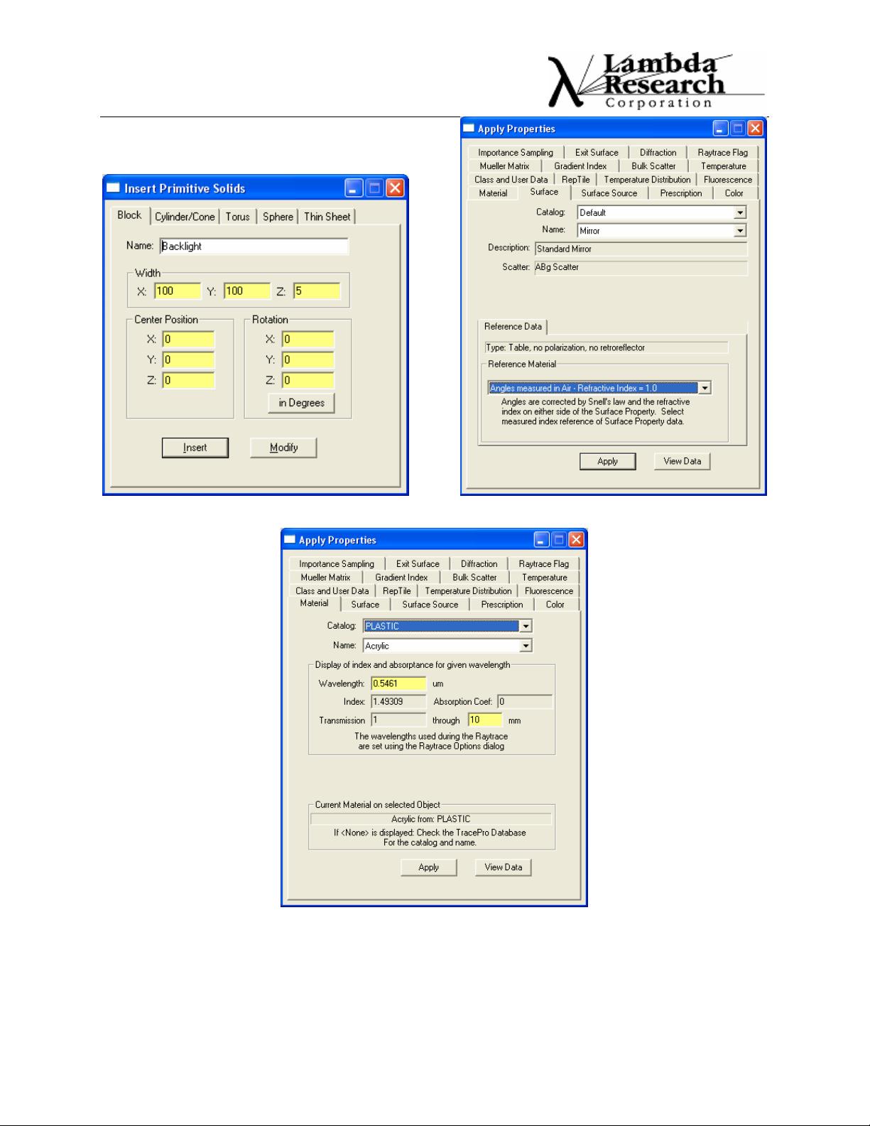
Backlight Geometry
A backlight for an LCD is at first level made of the following components:
• A thin sheet of plastic, such as acrylic, on which the back surface has structure
placed. A reflective coating can be added on three of the four edges, while the
remaining thin edge is at worst bare (i.e., anti-reflection coatings could be placed
here).
• A reflector is placed on the one bare edge such that it runs the length of the
plastic backlight. This reflector is some type of conic, such as circular, elliptical,
or parabolic. Its output aperture is matched to the size of the bare edge of the
plastic.
• A CCFL of small diameter is placed within the reflector. Positioning of the CCFL
is typically not critical except for its absorption of rays re-incident upon it.
• A highly reflective diffuser is placed below the plastic backlight. The bottom of
the backlight is the surface on which the Texture is placed.
• Finally, an observation plane is placed just above the output surface of the
backlight plastic. The output surface is the one opposite of the Textured surface.
There are a multitude of additional items that can be included in the model, including,
brightness enhancement films, a wedge on the plastic backlight, the liquid crystal
elements, additional diffusers, and the packaging around the backlight. For the
purposes of this tutorial, we will “simplify” the development to only include the elements
listed in the bulleted list above. Optimization of the system would include additional
elements, structure, and optical properties. The purpose is to show how to implement
Textured RepTile, and leave the optimization of the backlight to the user for their
desired application.
For the remainder of this tutorial, the following terms are used:
• Backlight = the thin sheet of plastic,
• Injector = the reflector that injects the light into the plastic,
• CCFL = the source placed within the injector,
• Feature = the individual spheres that are within the Texture file,
• Textures = the complete set of Features comprised by the Texture file,
Lambda Research Corporation 3
www.cadfamily.com EMail:cadserv21@hotmail.com
The document is for study only,if tort to your rights,please inform us,we will delete
TracePro Tutorial: Textured RepTile Backlight
• Diffuser = the highly reflective diffuser placed below the Textured surface of the
backlight, and
• Screen = the surface on which we sample the output distribution from the
backlight, where the term Observation indicates the surface on which we do this
sampling.
Creating the Backlight:
We first create a square acrylic backlight with dimensions of 100 mm x 100 mm x 5 mm
(XYZ). This solid is centered along the z direction. Figure 1 shows the dialog,
Insert>Primitive Solid…>Block, for this structure. We retain, at this time, the default
bare surfaces on the two large surfaces and the edge in the +y direction. As shown in
Fig. 2, for the three remaining surfaces we place the Mirror Surface property within the
Default Catalog. Here are the steps for the process described here:
1. Open a New model window,
2. Select Insert>Primitive Solid…>Block,
3. Enter the values as shown in Fig. 1,
4. Select Insert from the dialog,
5. Rescale the model window by first selecting the backlight and then
View>Zoom>Selection (
),
6. Select Backlight Surfaces 2, 3, and 5 with CTRL left clicks,
7. Right click on one of these three surfaces and select Properties… from the pop-
up menu, or select the icon
,
8. Select the Surface tab,
9. Enter the parameters as shown in Fig. 2,
10. Select Apply from the dialog,
11. Select the Material tab,
12. Enter the parameters as shown in Fig. 3,
13. Select Apply from the dialog,
14. You can Close the open dialogs, but it is not necessary,
15. Rename Surface 1 to Texture. To do this select it twice with a left click. When
a rectangle appears around its current name, enter the new name. This is the
surface on which we will later apply the Texture File, and
16. As per Fig. 4, inspect the System Tree such that the properties for Backlight are
as shown (Note: Fig. 4 also shows all of the other objects that we will define in
this section.)
Lambda Research Corporation 4
www.cadfamily.com EMail:cadserv21@hotmail.com
The document is for study only,if tort to your rights,please inform us,we will delete
TracePro Tutorial: Textured RepTile Backlight
Lambda Research Corporation 5
Figure 1. Parameters to Insert the Backlight. Figure 2. Apply properties for Mirror application.
Figure 3. Apply properties for the Backlight Material.
www.cadfamily.com EMail:cadserv21@hotmail.com
The document is for study only,if tort to your rights,please inform us,we will delete
剩余25页未读,继续阅读
qq_27137597
- 粉丝: 0
- 资源: 1
上传资源 快速赚钱
- 我的内容管理 收起
- 我的资源 快来上传第一个资源
- 我的收益 登录查看自己的收益
- 我的积分 登录查看自己的积分
- 我的C币 登录后查看C币余额
- 我的收藏
- 我的下载
- 下载帮助
会员权益专享
最新资源
- zigbee-cluster-library-specification
- JSBSim Reference Manual
- c++校园超市商品信息管理系统课程设计说明书(含源代码) (2).pdf
- 建筑供配电系统相关课件.pptx
- 企业管理规章制度及管理模式.doc
- vb打开摄像头.doc
- 云计算-可信计算中认证协议改进方案.pdf
- [详细完整版]单片机编程4.ppt
- c语言常用算法.pdf
- c++经典程序代码大全.pdf
- 单片机数字时钟资料.doc
- 11项目管理前沿1.0.pptx
- 基于ssm的“魅力”繁峙宣传网站的设计与实现论文.doc
- 智慧交通综合解决方案.pptx
- 建筑防潮设计-PowerPointPresentati.pptx
- SPC统计过程控制程序.pptx
资源上传下载、课程学习等过程中有任何疑问或建议,欢迎提出宝贵意见哦~我们会及时处理!
点击此处反馈
安全验证
文档复制为VIP权益,开通VIP直接复制
信息提交成功
评论0