
September 2009 Doc ID 14611 Rev 7 1/123
1
STM32F103xC STM32F103xD
STM32F103xE
High-density performance line ARM-based 32-bit MCU with 256 to
512KB Flash, USB, CAN, 11 timers, 3 ADCs, 13 communication interfaces
Features
■ Core: ARM 32-bit Cortex™-M3 CPU
– 72 MHz maximum frequency,
1.25 DMIPS/MHz (Dhrystone 2.1)
performance at 0 wait state memory
access
– Single-cycle multiplication and hardware
division
■ Memories
– 256 to 512 Kbytes of Flash memory
– up to 64 Kbytes of SRAM
– Flexible static memory controller with 4
Chip Select. Supports Compact Flash,
SRAM, PSRAM, NOR and NAND
memories
– LCD parallel interface, 8080/6800 modes
■ Clock, reset and supply management
– 2.0 to 3.6 V application supply and I/Os
– POR, PDR, and programmable voltage
detector (PVD)
– 4-to-16 MHz crystal oscillator
– Internal 8 MHz factory-trimmed RC
– Internal 40 kHz RC with calibration
– 32 kHz oscillator for RTC with calibration
■ Low power
– Sleep, Stop and Standby modes
–V
BAT
supply for RTC and backup registers
■ 3 × 12-bit, 1 µs A/D converters (up to 21
channels)
– Conversion range: 0 to 3.6 V
– Triple-sample and hold capability
– Temperature sensor
■ 2 × 12-bit D/A converters
■ DMA: 12-channel DMA controller
– Supported peripherals: timers, ADCs, DAC,
SDIO, I
2
Ss, SPIs, I
2
Cs and USARTs
■ Debug mode
– Serial wire debug (SWD) & JTAG interfaces
– Cortex-M3 Embedded Trace Macrocell™
■ Up to 112 fast I/O ports
– 51/80/112 I/Os, all mappable on 16
external interrupt vectors and almost all
5 V-tolerant
■ Up to 11 timers
– Up to four 16-bit timers, each with up to 4
IC/OC/PWM or pulse counter and
quadrature (incremental) encoder input
– 2 × 16-bit motor control PWM timers with
dead-time generation and emergency stop
– 2 × watchdog timers (Independent and
Window)
– SysTick timer: a 24-bit downcounter
– 2 × 16-bit basic timers to drive the DAC
■ Up to 13 communication interfaces
– Up to 2 × I
2
C interfaces (SMBus/PMBus)
– Up to 5 USARTs (ISO 7816 interface, LIN,
IrDA capability, modem control)
– Up to 3 SPIs (18 Mbit/s), 2 with I
2
S
interface multiplexed
– CAN interface (2.0B Active)
– USB 2.0 full speed interface
– SDIO interface
■ CRC calculation unit, 96-bit unique ID
■ ECOPACK
®
packages
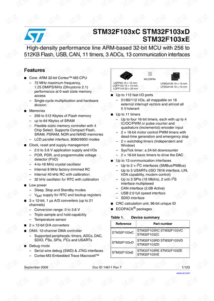
Table 1. Device summary
Reference Part number
STM32F103xC
STM32F103RC STM32F103VC
STM32F103ZC
STM32F103xD
STM32F103RD STM32F103VD
STM32F103ZD
STM32F103xE
STM32F103RE STM32F103ZE
STM32F103VE
FBGA
LQFP64 10 × 10 mm,
LQFP100 14 × 14 mm,
LQFP144 20 × 20 mm
LFBGA100 10 × 10 mm
LFBGA144 10 × 10 mm
WLCSP64
www.st.com


剩余122页未读,继续阅读

single104
- 粉丝: 9
- 资源: 7
 我的内容管理
收起
我的内容管理
收起
- 我的资源
快来上传第一个资源
 我的收益 登录查看自己的收益
 我的积分
登录查看自己的积分
我的积分
登录查看自己的积分
 我的C币
登录后查看C币余额
我的C币
登录后查看C币余额
 我的收藏
我的收藏  我的下载
我的下载  下载帮助
下载帮助

会员权益专享


最新资源
- zigbee-cluster-library-specification
- JSBSim Reference Manual
- c++校园超市商品信息管理系统课程设计说明书(含源代码) (2).pdf
- 建筑供配电系统相关课件.pptx
- 企业管理规章制度及管理模式.doc
- vb打开摄像头.doc
- 云计算-可信计算中认证协议改进方案.pdf
- [详细完整版]单片机编程4.ppt
- c语言常用算法.pdf
- c++经典程序代码大全.pdf
- 单片机数字时钟资料.doc
- 11项目管理前沿1.0.pptx
- 基于ssm的“魅力”繁峙宣传网站的设计与实现论文.doc
- 智慧交通综合解决方案.pptx
- 建筑防潮设计-PowerPointPresentati.pptx
- SPC统计过程控制程序.pptx
资源上传下载、课程学习等过程中有任何疑问或建议,欢迎提出宝贵意见哦~我们会及时处理!
点击此处反馈


