LPC55S6x嵌入式微控制器用户手册:Arm Cortex-M33与安全特性概览
需积分: 11 90 浏览量
更新于2024-07-16
收藏 13.18MB PDF 举报
LPC55S6x是一款基于Arm Cortex-M33架构的嵌入式微控制器,专为高性能和安全应用设计。这款微控制器具有强大的硬件特性,包括最高320kB的片内SRAM和640kB的片内闪存,支持高速和全速USB主机和设备接口,无需外部时钟即可实现全速功能。它还配备了一个SD/MMC/SDIO接口、五个通用定时器、一个SCTimer/PWM、一个RTC/报警定时器、一个24位多速率定时器(MRT)、一个窗口看门狗定时器(WWDT)、一个高速SPI接口(高达50MHz),以及八个灵活的串行通信外设,可以作为USART、SPI、I2C或I2S接口使用。
安全性是LPC55S6x的重要卖点,它配备了TrustZone技术,提供隔离保护,确保宝贵知识产权和数据的安全。Cortex-M33内核集成了数字信号处理(DSP)指令,简化了数字信号控制系统的设计和软件开发。为了满足安全需求,该微控制器支持各种加密算法,如哈希(HASH)、AES、RSA、UUID的处理,以及动态加密解密功能。此外,还提供了调试认证和TBSA合规性支持。
文档还涵盖了其他关键功能,如电源管理、PLU(Power Logic Unit)、CASPER(嵌入式安全启动模块)、以及用于传感器输入的16位1.0 Msamples/sec的ADC和温度传感器。在文档的系统配置部分(Chapter 4 "LPC55S6x SYSCON"),提供了详细的系统设置选项和更新信息,帮助用户优化设备性能。
文档版本历史表明,自2019年发布以来,LPC55S6x User Manual经历了多次迭代,增加了新的功能和改进,以适应不断变化的需求和技术发展。用户在查阅时应注意查看最新的修订版以获取最新信息。
LPC55S6x是一款功能强大、安全性高且高度可扩展的微控制器,适用于需要高效处理、快速通信和高级安全性的各种嵌入式系统项目。开发者可以根据其丰富的特性选择合适的配置,并利用其内置的优化工具和安全特性来构建可靠的产品。

UM11126 All information provided in this document is subject to legal disclaimers. © NXP Semiconductors N.V. 2019. All rights reserved.
User manual Rev. 1.3 — 10 May 2019 16 of 1148
3.1 How to read this chapter
Available interrupt sources may vary with specific LPC55xx device types.
3.2 Features
• Nested Vectored Interrupt Controller (NVIC) is an integral part of each CPU.
• Tightly coupled interrupt controller provides low interrupt latency.
• Controls system exceptions and peripheral interrupts.
• The NVIC of the Cortex-M33 supports:
– 64 vectored interrupt slots
.
– Eight programmable interrupt priority levels with hardware priority level masking.
– Vector table offset register VTOR.
– Software interrupt generation.
– Support for NMI from any interrupt, see Section 21.4.3
.
3.3 General description
The tight coupling to the NVIC to the CPU allows for low interrupt latency and efficient
processing of late arriving interrupts.
3.3.1 Interrupt sources
Tabl e 7 lists the interrupt sources for each peripheral function. Each peripheral device
may have one or more interrupt lines to the Vectored Interrupt Controller. Each line may
represent more than one interrupt source. The interrupt number does not imply any
interrupt priority when interrupts are not given the same priority. In the case, where two
interrupts for example are given the same priority, then the interrupt number below is
relevant.
See Ref. 1 “
Cortex-M33 DGUG” for detailed descriptions of the NVIC and the NVIC
registers.
UM11126
Chapter 3: LPC55S6x Nested Vectored Interrupt Controller
(NVIC)
Rev. 1.3 — 10 May 2019 User manual
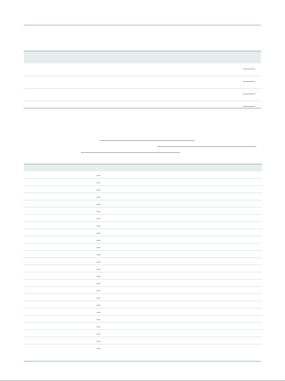
Table 7. Connection of interrupt sources to the NVIC
Interrupt Name Interrupt description Flags
0WDT
BOD
FLASH
Windowed watchdog timer, Brown Out Detect,
Flash controller.
WARNINT - watchdog warning
interrupt
BODINTVAL - BOD interrupt
level.
1 SDMA0 SDMA0 controller. Interrupt A and interrupt B, error
interrupt.
2 GPIO_GLOBALINT0 GPIO group 0. Enabled pin interrupts.
3 GPIO_GLOBALINT1 GPIO group 1. Enabled pin interrupts.


剩余1147页未读,继续阅读
2021-05-20 上传
2022-01-03 上传
2009-12-08 上传
2021-09-15 上传
2020-01-17 上传
2019-06-18 上传
2011-11-27 上传
2020-08-28 上传
2020-08-09 上传


书香度年华
- 粉丝: 1w+
- 资源: 383
 我的内容管理
展开
我的内容管理
展开


最新资源
- 基于Python和Opencv的车牌识别系统实现
- 我的代码小部件库:统计、MySQL操作与树结构功能
- React初学者入门指南:快速构建并部署你的第一个应用
- Oddish:夜潜CSGO皮肤,智能爬虫技术解析
- 利用REST HaProxy实现haproxy.cfg配置的HTTP接口化
- LeetCode用例构造实践:CMake和GoogleTest的应用
- 快速搭建vulhub靶场:简化docker-compose与vulhub-master下载
- 天秤座术语表:glossariolibras项目安装与使用指南
- 从Vercel到Firebase的全栈Amazon克隆项目指南
- ANU PK大楼Studio 1的3D声效和Ambisonic技术体验
- C#实现的鼠标事件功能演示
- 掌握DP-10:LeetCode超级掉蛋与爆破气球
- C与SDL开发的游戏如何编译至WebAssembly平台
- CastorDOC开源应用程序:文档管理功能与Alfresco集成
- LeetCode用例构造与计算机科学基础:数据结构与设计模式
- 通过travis-nightly-builder实现自动化API与Rake任务构建
