英飞凌TLE9879芯片评估套件用户手册
需积分: 5 64 浏览量
更新于2024-06-25
收藏 3.27MB PDF 举报
英飞凌 TLE9879 芯片手册
本文档是英飞凌 TLE9879 芯片的手册,提供了该芯片的详细信息和使用指南。本文档将从概念、互连、测试点、通信接口、技术数据、可选添加元件、版本变化、电路图和布局等方面详细介绍 TLE9879 芯片。
一、概念
TLE9879 芯片是英飞凌公司生产的一款高性能微控制器,具有高效、低功耗和高可靠性的特点。该芯片广泛应用于汽车电子、工业控制、消费电子等领域。
二、互连
TLE9879 芯片具有多种互连方式,包括 LIN 总线、UART、SPI 等。这些互连方式可以满足不同的应用需求,例如车联网、智能家居、工业自动化等。
三、测试点
TLE9879 芯片提供了多个测试点,用于调试和测试芯片的性能。这些测试点包括电压、电流、温度等参数,可以帮助开发者快速地调试和优化芯片的性能。
四、通信接口
TLE9879 芯片提供了多种通信接口,包括 LIN、UART、SPI 等。这些通信接口可以满足不同的应用需求,例如车联网、智能家居、工业自动化等。
五、技术数据
TLE9879 芯片具有高效、低功耗和高可靠性的特点。该芯片的技术数据包括电压范围、电流范围、温度范围等参数,可以帮助开发者快速地了解芯片的性能。
六、可选添加元件
TLE9879 芯片提供了多种可选添加元件,例如电感、电阻、电容等。这些元件可以根据不同的应用需求进行选择和添加,从而满足不同的应用需求。
七、版本变化
TLE9879 芯片的版本变化包括反向极性保护、电路图和布局的变化等。这些变化可以帮助开发者快速地了解芯片的变化和升级。
八、电路图和布局
TLE9879 芯片的电路图和布局提供了详细的设计指南,可以帮助开发者快速地设计和实现芯片的应用系统。
TLE9879 芯片手册提供了详细的信息和使用指南,可以帮助开发者快速地了解和使用该芯片。
TLE9879 EvalKit V1.3 User Manual 4
3 Interconnects
Figure 2: Interconnects
Banana jacks (marked yellow)
There are jacks in different colors for ground, supply (max.28V) and LIN communication via banana jack: GND
(black), VBAT (red), LIN (green)
Pin Ports X4 and X5 (marked red)
Soldering pin headers with 2,54mm pitch for X4 (1x10) and X5(1x16) yields test points for the TLE9879 pins. The
following signals are connected to the pins:
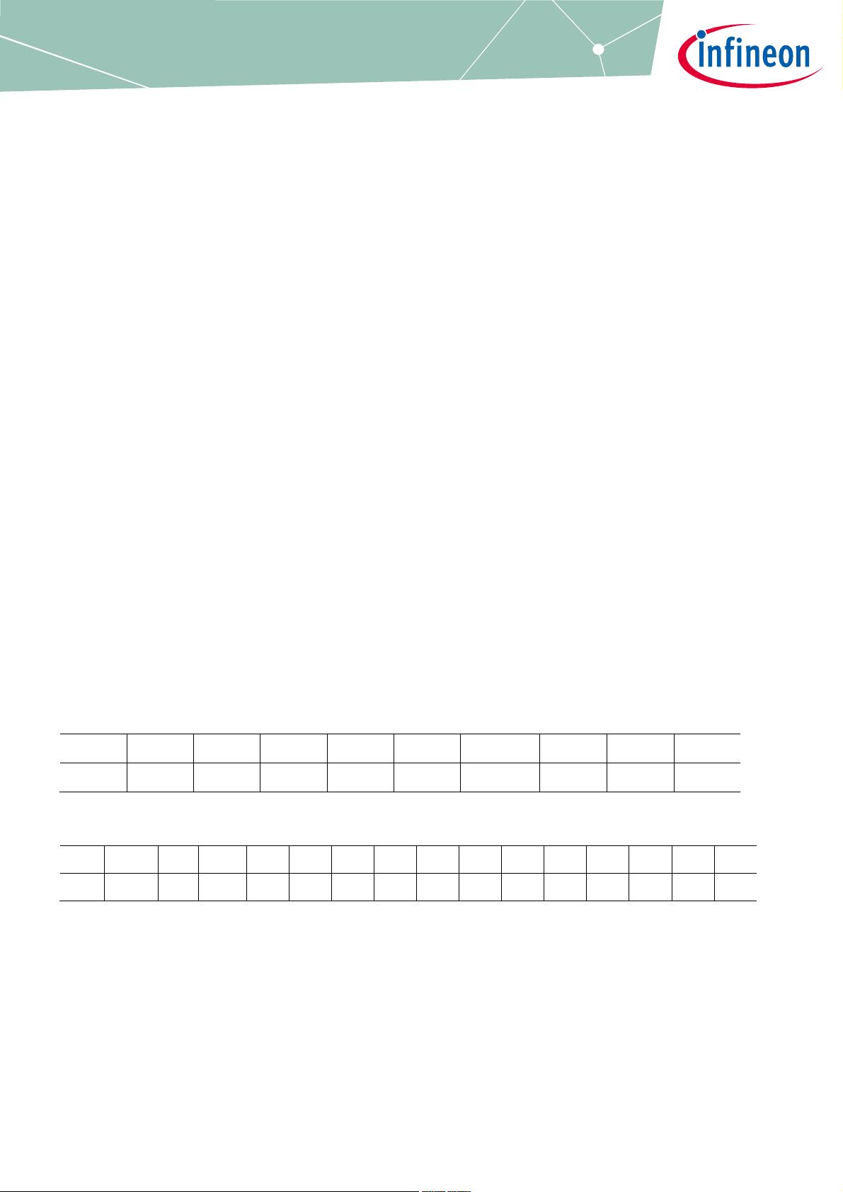
X4:
1 2 3 4 5 6 7 8 9 10
GND VCP VSD VS VDH LIN VDDEXT VDDP VAREF GND
Table 2: Pin Configuration Top Line Pin Port (X4)
X5:
1 2 3 4 5 6 7 8 9 10 11 12 13 14 15 16
GND MON RST P0.0 P1.1 P0.1 P0.2 P0.3 P1.2 P1.0 P1.3 P1.4 P0.4 P2.3 P2.4 P2.5
Table 3: Pin Configuration Bottom Line Pin Port (X5)
Terminal block for connecting the motor (marked blue)
The three pins of the terminal block provide access to the three half bridges and are intended to connect a DC
brushless motor.
USB for UART and Debugging (marked green)
With this Micro USB PC and evaluation board can get connected.
剩余17页未读,继续阅读
2021-04-20 上传
2022-07-15 上传
2020-11-08 上传
2021-06-26 上传
2022-08-28 上传
2021-03-13 上传
2023-07-18 上传
2023-07-18 上传

&春风有信
- 粉丝: 1w+
- 资源: 37
 我的内容管理
展开
我的内容管理
展开


