CoDeSys引导:实践IEC 61131-3编程语言在PLC中的差异与应用
《可编程逻辑控制器:基于IEC 61131-3的CoDeSys实用方法》是一本由John R. Hackworth和Frederick D. Hackworth Jr.合著的实用指南,着重于介绍PLC(Programmable Logic Controller)编程方法及其应用。自PLC市场出现竞争以来,不同品牌间的编程语言差异日益显著,尽管早期的标准如指令列表(Instruction Lists, IL)和梯形图(Ladder Diagram, LD)被广泛应用,但每个制造商都对这些基础语言进行了自家的扩展,形成了各自的“方言”。
该书内容广泛,共分为12章,旨在提供一个全面的学习平台,而非局限于单一制造商的产品。第1章介绍了梯形图基础,这是PLC编程中最基本的概念,用于描述设备的工作流程。接着,作者探讨了PLC的基本概念,包括其在工业自动化中的角色和功能。
第3章深入到PLC的实际编程技巧,讲解如何利用各种编程语言如结构文本(Structured Text, ST)、功能块图(Function Block Diagram, FBD)等,这些是根据IEC 61131-3国际标准制定的五种标准编程语言之一。CoDeSys是一个跨平台的工具集,允许用户使用这些标准化的语言在多种PLC上进行编程,从而提高了兼容性和效率。
随着章节的推进,书中涵盖了高级编程技术,如助记符编程代码(Mnemonic Programming Code),这有助于程序员更高效地编写程序;第6章讨论了接线技术,强调了实际安装和布线在控制系统设计中的重要性;第7章和后续章节分别关注模拟输入/输出、离散位置传感器、编码器、变送器等,以及高级传感器的应用。
第10章和11章深入到闭环控制和电机控制的实现,包括PID(Proportional-Integral-Derivative)控制,这是工业自动化中常见的控制策略。最后,第12章着重于系统的完整性和安全性,探讨了如何确保PLC系统在复杂工业环境中的稳定运行和防护措施。
《Programmable Logic Controllers: A Practical Approach to IEC 61131-3 Using CoDeSys》是一本实用的教材,不仅教授基础知识,还帮助读者理解和掌握多种编程方法,以适应不同厂商的PLC产品,并熟悉国际标准IEC 61131-3。通过本书,学习者不仅能学会特定设备的编程,还能提升跨平台工作的能力,对于从事PLC编程或工业自动化领域的专业人士来说,具有很高的参考价值。
Chapter 1 - Ladder Diagram Fundamentals
1-13
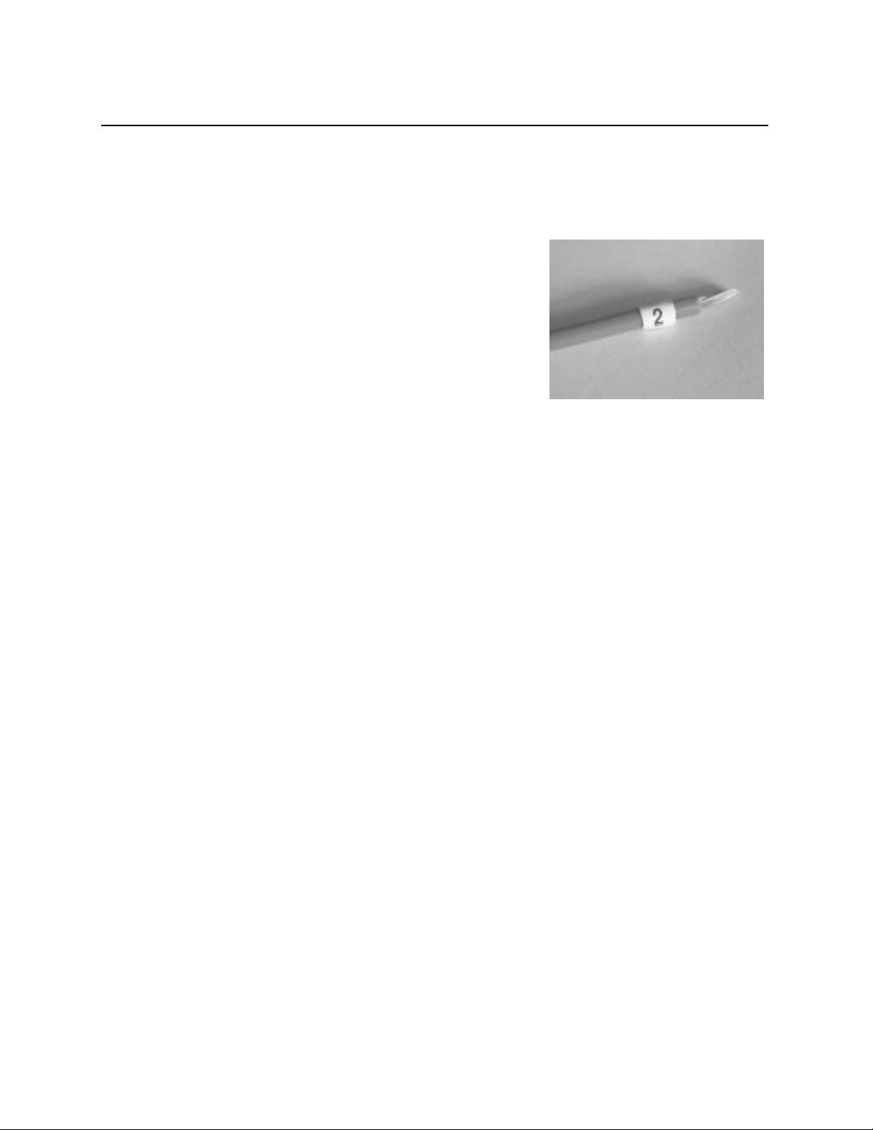
Figure 1-19 - Wire Marker
or white wire (do not use green - it is reserved for safety ground wiring). Notice that in
Figure 1-18 the wire connecting T1 to F1 is not numbered. This is because in our design
we will be using a transformer with the fuse block included. Therefore, this will be a
permanent metal strap on the transformer and will not be a wire.
The wire generally used within the controls circuitry
is AWG14 or AWG16 stranded copper, type MTW or THHN.
MTW is an abbreviation for “machine tool wire” and THHN
indicates thermoplastic heat-resistant nylon-coated. MTW
has a single PVC insulation jacket and is used in
applications where the wire will not be exposed to gas or oil.
It is less expensive, more flexible, and easier to route,
bundle, and pull through conduits. THHN is used in areas
where the wire may be exposed to gas or oil (such as
hydraulically operated machines). It has a transparent, oil-
resistant nylon coating on the outside of the insulation. The drawback to THHN is that it
is more expensive, is more difficult to route around corners, and because of its larger
diameter, reduces the maximum number of conductors that can be pulled into tight places
(such as inside conduits). Since most control components use low currents, AWG14 or
AWG16 wire is much larger than is needed. However, it is generally accepted for panel
and controls wiring because the larger wire is tough, more flexible, easier to install, and can
better withstand the constant vibration created by heavy machinery.
Reference Designators
For all electrical diagrams, every component is given a reference designator. This
is a label assigned to the component so that it can be easily located. The reference
designator for each component appears on the schematic diagram, the mechanical layout
diagram, the parts list, and sometimes is even stamped on the actual component itself.
The reference designator consists of an alphabetical prefix followed by a number. The
prefix identifies what kind of part it is (control relay, transformer, limit switch, etc.), and the
number indicates which particular part it is. Some of the most commonly used reference
designator prefixes are as follows:
T transformer
CR control relay
Rresistor
C capacitor
LS limit switch
PB pushbutton
S switch
SS selector switch


剩余270页未读,继续阅读
2015-11-26 上传
2016-12-07 上传
2011-08-04 上传
2021-10-01 上传
2012-08-11 上传
2021-10-03 上传
2013-05-22 上传
2021-09-11 上传
2021-09-11 上传

sonictrain
- 粉丝: 0
- 资源: 5
 我的内容管理
展开
我的内容管理
展开


最新资源
- 俄罗斯RTSD数据集实现交通标志实时检测
- 易语言开发的文件批量改名工具使用Ex_Dui美化界面
- 爱心援助动态网页教程:前端开发实战指南
- 复旦微电子数字电路课件4章同步时序电路详解
- Dylan Manley的编程投资组合登录页面设计介绍
- Python实现H3K4me3与H3K27ac表观遗传标记域长度分析
- 易语言开源播放器项目:简易界面与强大的音频支持
- 介绍rxtx2.2全系统环境下的Java版本使用
- ZStack-CC2530 半开源协议栈使用与安装指南
- 易语言实现的八斗平台与淘宝评论采集软件开发
- Christiano响应式网站项目设计与技术特点
- QT图形框架中QGraphicRectItem的插入与缩放技术
- 组合逻辑电路深入解析与习题教程
- Vue+ECharts实现中国地图3D展示与交互功能
- MiSTer_MAME_SCRIPTS:自动下载MAME与HBMAME脚本指南
- 前端技术精髓:构建响应式盆栽展示网站
