


LTE信号调试与优化权威指南:协议详解与故障诊断
需积分: 10 107 浏览量
更新于2024-07-18
收藏 34.06MB PDF 举报
"LTE Signaling, Troubleshooting, and Optimization是由Ralf Kreher和Karsten Gaenger合著的一本详尽的4G网络技术参考书籍,于2011年首次出版。本书专注于第四代移动通信(4G)中的长期演进(Long Term Evolution, LTE)网络的呼叫流程、信令、故障诊断和优化。它全面涵盖了从基本性能测量计数器、无线质量到用户平面质量,以及不同接口的标准、架构、目标和功能等核心概念。
书中首先概述了LTE/演进分组核心网(Evolved Packet Core, EPC)的网络架构、参考点、协议栈、信息元素和基本操作过程。随后的内容深入探讨了更高级的主题,包括LTE/EPC信令分析和无线质量评估,旨在帮助读者理解正常和异常网络行为的信号流程,并识别和解决常见故障的原因。
该书不仅补充了3GPP标准提供的信息,还提供了一个通用的LTE/EPC协议序列,确保读者对涉及的问题有清晰的理解。对于监控UMTS网络的人员来说,它解释了在监测时需要分析的信令程序和参数。作者通过真实LTE/EPC跟踪数据提供了第一手资料,使读者能够掌握信令程序的基础知识,甚至对测试和测量专家来说,提供了详细级别的分析指南。
此外,本书还包括了对LTE空口监视场景的描述,以及其他高级主题,如优化策略和方法。作为UMTS信令和性能测量系列的后续之作,LTE Signaling, Troubleshooting, and Optimization是研究4G网络性能、调试和提升的理想参考书籍,特别适合那些需要深入了解这一领域的专业人士。版权信息遵循英国《版权、设计和专利法》1988年的规定,所有权利受到保护,未经许可,不得任何形式复制、存储或传输。"
6 LTE Signaling, Troubleshooting and Optimization
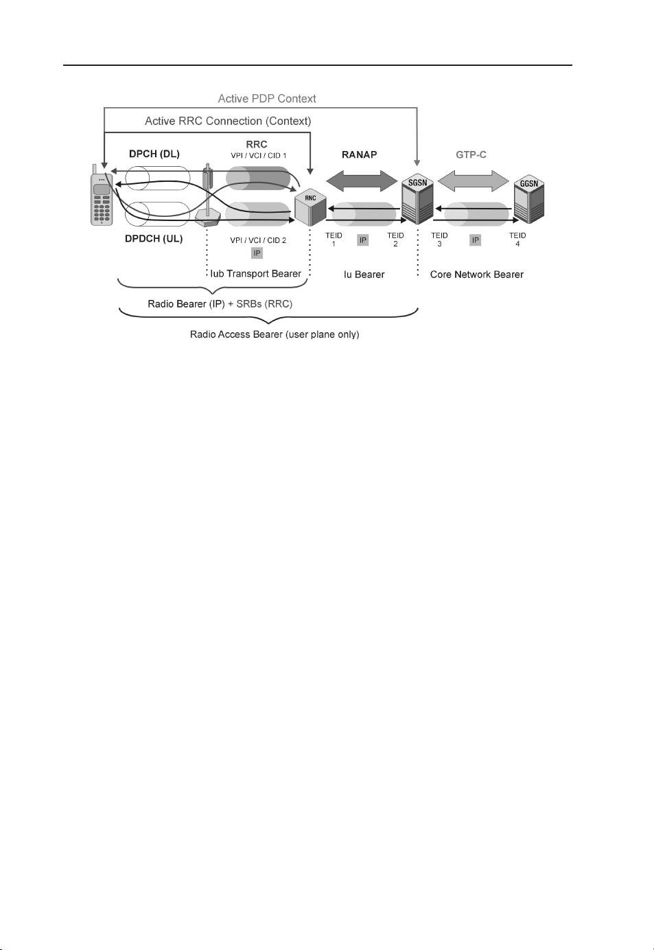
Figure 1.7 IP payload transmission using Release 99 bearers with UE in CELL_DCH state.
Since these early days two key parameters have driven the evolution of packet services further
toward LTE: higher data rates and shorter latency. EGPRS (or EDGE) focused mostly on higher
bit rates, but did not include any latency requirements or algorithms to guarantee a defined Quality
of Service (QoS) in early standardization releases. Meanwhi le, i n parallel to the development of
UMTS standards, important enhancements to EDGE have been defined that allow pre-emption of
radio resources for packet services and control of QoS. Due to its easy integration in existing GSM
networks, EDGE is widely deployed today in cellular networks and is expected to coexist with LTE
on the long haul.
Nevertheless, the first standard that promised complete control of QoS was UMTS Release 99. In
contrast to the TBFs of (E)GPRS, the user is assigned dedicated radio resources for PS data that are
permanently available through a radio connection. These resources are called bearers.
In Release 99, when a PDP (Packet Data Protocol) context is act ivated the UE is ordered by the RNC
(Radio Network Controller) to enter the Radio Resource Control (RRC) CELL_DCH state. Dedicated
resources are assigned by the Serving Radio Network Controller (SRNC): these are the dedicated
physical channels established on the radio interface. Those channels are used for transmission of both
IP payload and RRC signaling – see Figure 1.7. RRC signaling includes the exchange of Non-Access
Stratum (NAS) messages between the UE and SGSN.
The spreading factor of the radio bearer (as the combination of several physical transport resources
on the Air and Iub interfaces is called) depends on the expected UL/DL IP t hroughput. The expected
data transfer rate can be found in the RANAP (Radio Access Network Application Part) part of
the Radio Access Bearer (RAB) assignment request message that i s used to establish the Iu bearer,
a GPRS Tunneling Protocol (GTP) tunnel for transmission of a IP payload on the IuPS interface
between SRNC and SGSN. While the spreading factor controls the bandwidth of the radio connection,
a sophisticated power control algorithm guarantees the necessary quality of the radio transmission.
For instance, this power control ensures that th e number of retransmitted frames does not exceed a
certain critical threshold.
Activation of PDP context results also in the establishment of another GTP tunnel on the Gn
interface between SGSN and GGSN. In contrast to IuPS, where tunnel management is a task of
RANAP, on the Gn interface – as in (E)GPRS – the GPRS Tunneling Protocol – Control (GTP-C) is
responsible for context (or tunnel) activation, modification, and deletion.

剩余290页未读,继续阅读
632 浏览量
2025-03-26 上传
2025-03-26 上传
2025-03-26 上传
2025-03-26 上传
2025-03-26 上传
2025-03-26 上传
2025-03-26 上传

叫我大师
- 粉丝: 0
 我的内容管理
展开
我的内容管理
展开


最新资源
- STM32外部中断控制外设DEMO演示
- NSIS安装程序制作及代码注释解读
- Android系统日程管理应用开发与时间设置技巧
- C#.NET 2.0实现高效大文件下载方法
- C#实现泛型快速排序方法详解
- 掌握ASP.NET:深入理解程序设计基础
- 99健康网触屏版WAP网站模板:前端至大数据源码下载
- OpenGL基础示例:掌握图形编程
- 掌握Python正则表达式,提升爬虫效率
- 深入解析zthread2.3.2源码与库文件的使用
- uni-app初学者登录案例入门指南
- JG-KB3000S矩阵管理软件深度解析
- 个人免费版365USB锁:全面保护数据安全
- LEX Ad Blocker-crx插件:优化Salesforce使用体验
- PHP源码项目:民间验方大全及各类技术项目资源
- 映泰945GZ主板刷机BIOS详细教程