英飞凌HybridPACK 2 IGBT驱动技术手册
需积分: 48 64 浏览量
更新于2024-07-23
8
收藏 3.92MB PDF 举报
"英飞凌IGBT驱动经典——HybridKit for HybridPACK™2应用笔记"
本文档是英飞凌科技公司发布的关于IGBT驱动的经典应用资料,版本为V2.2,发布日期为2010年3月。文档主要介绍了针对HybridPACK™2模块的混合动力套件(HybridKit)的评估套件,适用于采用HybridPACK™2模块的应用。HybridPACK™是一种先进的模块化解决方案,常用于电力电子领域,尤其是混合动力和电动汽车的逆变器系统。
英飞凌作为全球领先的半导体公司,提供广泛的功率半导体产品,其中包括IGBT(绝缘栅双极晶体管)驱动技术。IGBT是电力转换和控制中的关键元件,因其高效、低损耗和高耐压特性,在工业、汽车和家用电器等领域有着广泛应用。
在本应用笔记中,读者可以了解到如何正确地设计和使用英飞凌的IGBT驱动电路,以确保高效、稳定的工作。内容可能涵盖以下几个方面:
1. IGBT驱动原理:解释了IGBT的工作机制,包括其开关特性和驱动要求,以及如何通过适当的驱动电路来优化其性能。
2. HybridPACK™2模块介绍:详细说明了该模块的结构、电气特性、热管理及封装技术,帮助设计者理解如何在实际应用中集成该模块。
3. 混合动力套件(HybridKit):描述了评估套件的功能、组成和使用方法,为开发者提供了一个快速评估和调试HybridPACK™2模块驱动方案的平台。
4. 设计指南:提供了实用的设计建议和注意事项,包括电磁兼容性(EMC)、热设计、保护电路等,以避免潜在的问题并提高系统可靠性。
5. 安全警告与合规性:提醒用户注意可能存在的技术要求,如组件可能含有有害物质,并指出应联系英飞凌获取更多信息。
6. 联系信息与支持:鼓励用户通过访问英飞凌官方网站或联系最近的办事处获取更多技术、交付条款、条件和价格等相关信息。
这份"英飞凌IGBT驱动经典"文档对于理解和开发基于英飞凌HybridPACK™2模块的电力电子系统具有极高的参考价值,无论你是资深工程师还是初学者,都能从中获得宝贵的知识和实践经验。
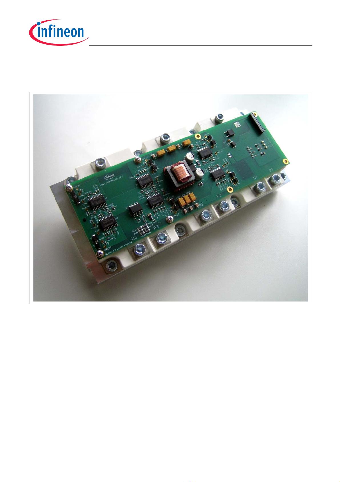
Hybrid Kit for HybridPACK™2
Evaluation Kit for Applications with HybridPACK™2 Module
Design Features
Application Note 16 V2.2, 2010-03
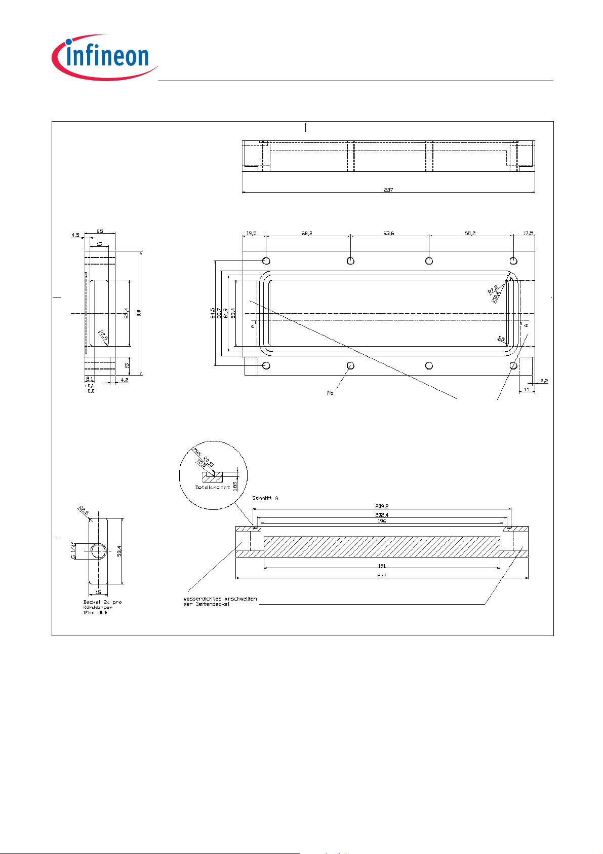
Figure 7 Water Cooling System Technical Drawings

剩余93页未读,继续阅读
2018-09-29 上传
2014-05-29 上传
2021-09-18 上传
2024-05-09 上传
2022-01-17 上传
点击了解资源详情
点击了解资源详情
2013-09-01 上传

michaelyun
- 粉丝: 1
- 资源: 3
 我的内容管理
展开
我的内容管理
展开


最新资源
- C语言数组操作:高度检查器编程实践
- 基于Swift开发的嘉定单车LBS iOS应用项目解析
- 钗头凤声乐表演的二度创作分析报告
- 分布式数据库特训营全套教程资料
- JavaScript开发者Robert Bindar的博客平台
- MATLAB投影寻踪代码教程及文件解压缩指南
- HTML5拖放实现的RPSLS游戏教程
- HT://Dig引擎接口,Ampoliros开源模块应用
- 全面探测服务器性能与PHP环境的iprober PHP探针v0.024
- 新版提醒应用v2:基于MongoDB的数据存储
- 《我的世界》东方大陆1.12.2材质包深度体验
- Hypercore Promisifier: JavaScript中的回调转换为Promise包装器
- 探索开源项目Artifice:Slyme脚本与技巧游戏
- Matlab机器人学习代码解析与笔记分享
- 查尔默斯大学计算物理作业HP2解析
- GitHub问题管理新工具:GIRA-crx插件介绍
